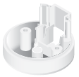
Package Contents
 |
|---|
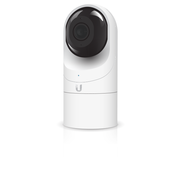
| Camera |
 |
|---|
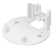
| Flush Mount |
 |
|---|
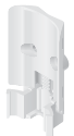
| Pole/Wall Mount |
 |
|---|
| Outdoor Cover |
 |
|---|
| Security Screw (Qty. 1) |
 |
|---|
| Screws (Qty. 3) |
 |
|---|
| Screw Anchors (Qty. 3) |
 |
|---|
| Zip Ties (Qty. 2) |
Installation Requirements
- Phillips screwdriver
- Drill and 6 mm (1/4") bit for drywall anchors and 3 mm (1/8") for screws)
- Category 5e (or above) Ethernet cable

|
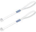
Note: When using the Outdoor Cover, use an Ethernet cable without a strain-relief boot on the connector. This will prevent unnecessary tension on the cable ends during installation. |
|---|
|
|
|
|
Cable without a strain-relief boot |
Cable with a strain-relief boot |


Outdoor Installation Requirements
|
|
IMPORTANT: When installed outdoors, the camera must be installed in the upright postion only. |
|---|

- Mounting location should be at least 60 cm (2 ft) from the edge of the eave or ceiling.
- Mount the camera in the upright position only. Please see diagram below.
- Shielded Category 5e (or above) cabling with drain wire should be used for all outdoor wired Ethernet connections and should be grounded through the AC ground of the PoE.
We recommend that you protect your networks from harmful outdoor environments and destructive ESD events with industrial-grade, shielded Ethernet cable from Ubiquiti. For more details, visit ui.com/toughcable
- Surge protection should be used for all outdoor installations. We recommend that you use two Ethernet Surge Protectors, model ETH-SP-G2, one near the UVC-G3-Flex and the other at the entry point to the building. The ETH-SP-G2 will absorb power surges and safely discharge them into the ground.
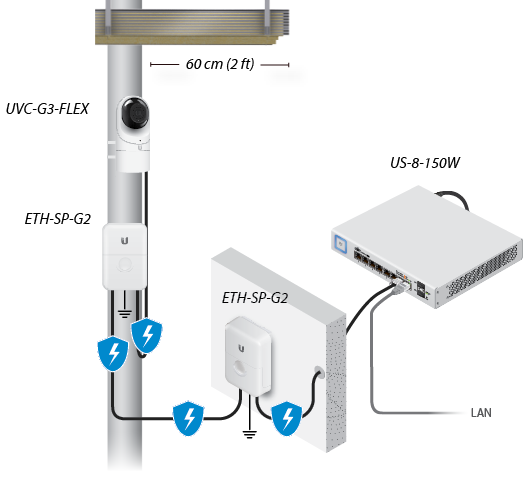
Diagram Showing Use of Ethernet Surge Protectors
Hardware Overview
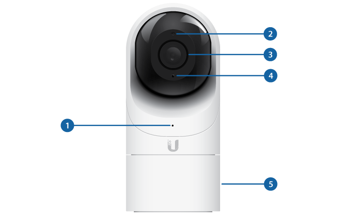
 LED |
|
|---|---|
Alternating White/Blue |
Device is busy; do not touch or unplug it. This usually indicates that a process such as a firmware upgrade is taking place. |
|
Steady Blue |
Connected to UniFi Protect Controller; Reset Button Pressed |
|
Flashing Green |
Disconnected from Controller |
|
Steady White |
Awaiting adoption |
 Microphone |
|
Microphone for recording audio |
|
 Camera Lens |
|
Lens for viewing/recording video |
|
 Light Sensor |
|
Sensor for ambient light detection |
|
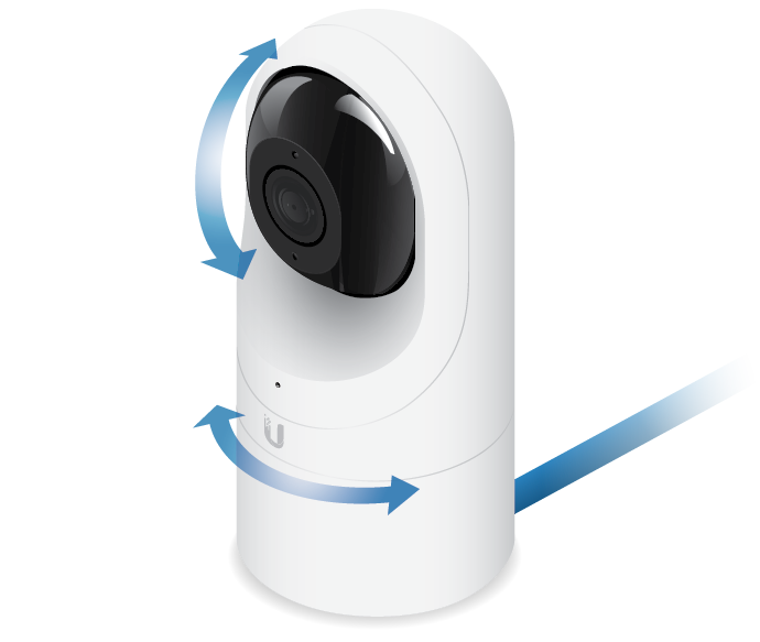
 Swivel Base |
|
Allows you to change the viewing angle of the camera by adjusting left or right. Useful if mounted on a wall or other permanent surface. |
|
Bottom View
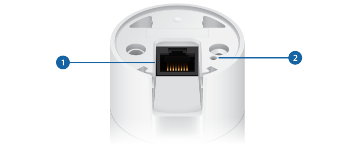
Ethernet Port |
|---|
The Ethernet Port is a 10/100 Mbps port used to supply power from a PoE 802.3af-compliant switch to the camera. The switch should be connected to a LAN running DHCP services and the UniFi Protect Controller software. |
Reset Button |
The Reset Button is used to reset the camera to factory defaults. Press and hold the Reset Button for more than 10 seconds while the camera is powered on. |
Mounting Options
|
|
Use the Flush Mount by itself to install the G3 Flex camera on a desktop or tabletop. Out of the box, this mount comes preinstalled on the camera. |
|
|
Use the Flush Mount with two screws to install the G3 Flex camera on a wall (vertically). |
|
|
Use the Flush Mount with two screws to install the G3 Flex camera on a solid horizontal surface or ceiling. |
|
|
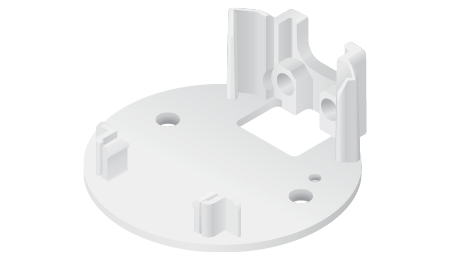
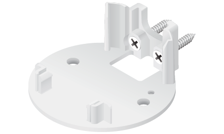
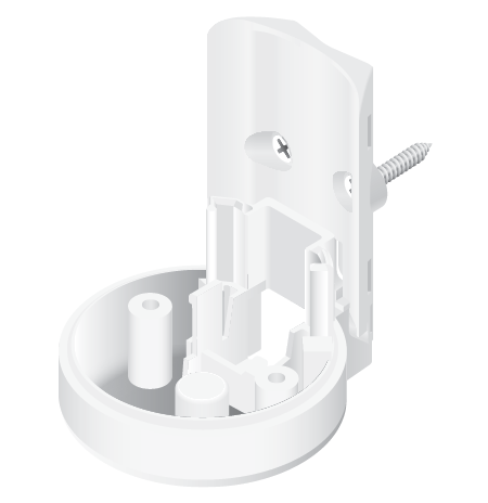
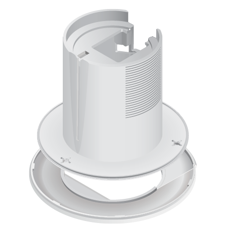
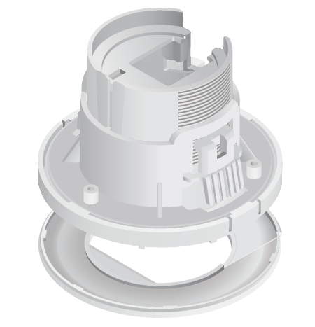
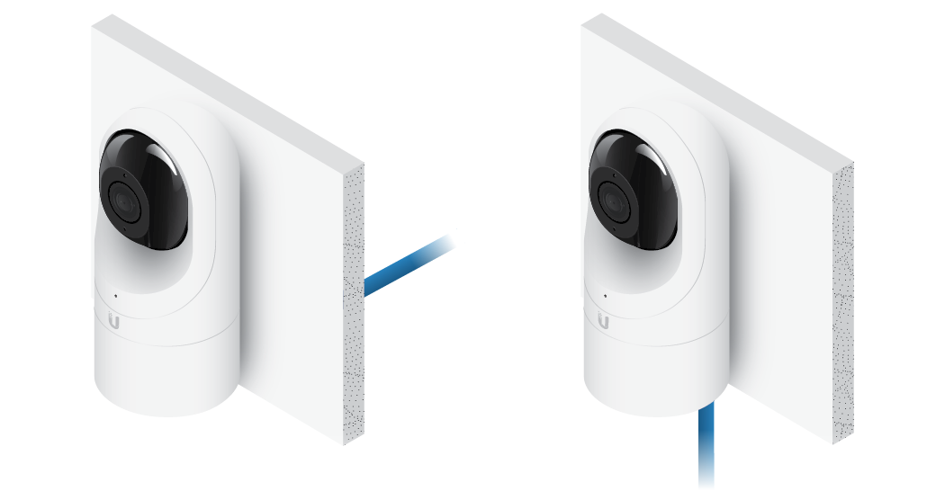
Use the Pole Mount with two screws and the Outdoor Cover to install the G3 Flex camera on a wall or flat surface outdoors. The Outdoor Cover is not required for indoor installations. |
|
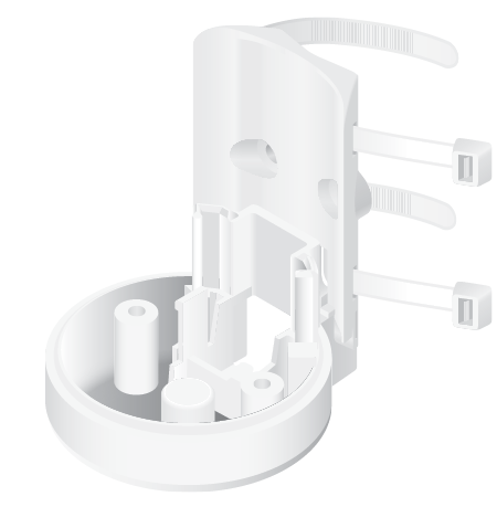
|
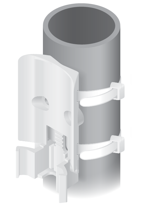
Use the Pole Mount with two plastic zip ties and the Outdoor Cover to install the G3 Flex camera on an outdoor pole. The Outdoor Cover is not required for indoor pole installations. |
Additional Mounts Available
There are two additional mounts available for the G3 Flex: a Ceiling Mount and a Pendant Mount. Each is sold separately.
|
|
Use the optional Ceiling Mount, Screw Kit, and Mount Cover to install the G3 Flex camera on a solid horizontal surface or ceiling. |
|
|
Use the optional Ceiling Mount, Mount Cover, and Back Plate Assembly to install the G3 Flex camera on a drop tile ceiling or horizontal surface where the interior side of the Ceiling Mount is accessible. |
|
|
Use the Pendant Mount to install the G3 Flex camera onto a fitted 3/4" or 1.5" conduit mount or ceiling pipe. |
Installation
The UVC G3 Flex can be installed using one of the following methods:
- Desktop For installing on a flat surface such as a desktop or table/shelf; could be set up for temporary installations.
- Wall/Ceiling For installing in a secure location; used more for stationary or permanent installations.
- Pole For installing on a pole (indoor or outdoor).
Proceed to the appropriate section for your installation.
|
|
Note: The viewing angle or surveillance coverage of the G3 Flex camera can be changed at any time.
|
|---|

Desktop
- Remove the Flush Mount from the bottom of the camera.
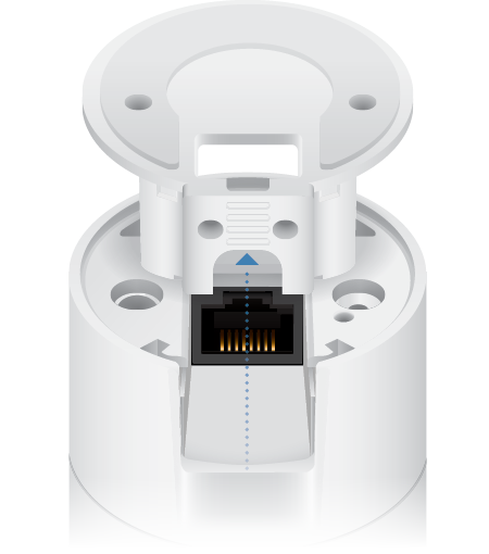
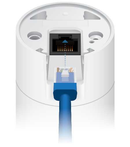
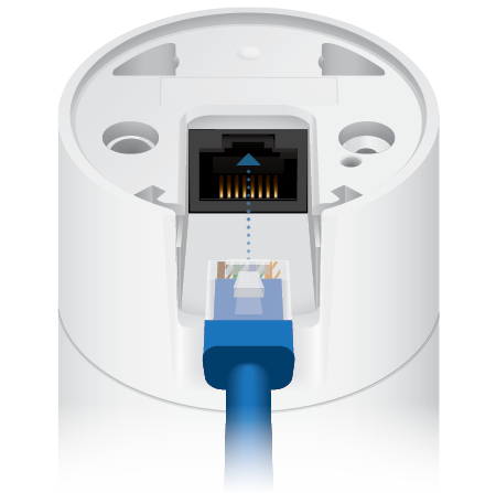
- Insert one end of the RJ-45 cable into the Ethernet Port and the other end into a PoE 802.3af-compliant switch.
- Attach the camera to the Flush Mount by lining up the notches with the slots in the base of the camera. Press firmly together until the camera is secure.
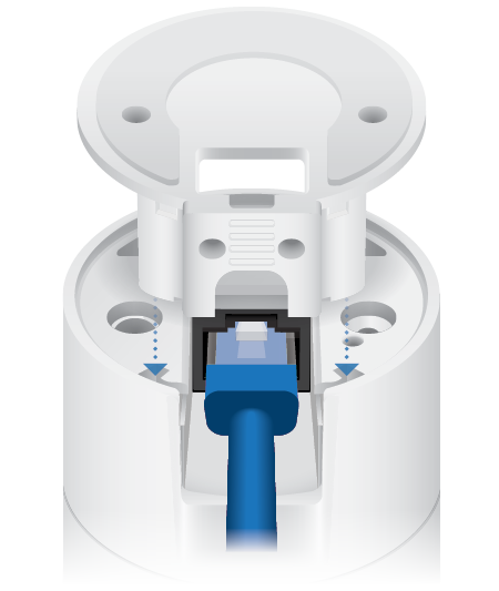
Note: Ensure the Ethernet cable is seated in the notch between the Flush Mount and base of the camera.
- Place the camera on a desk or table in its upright position.
- Adjust the viewing angle or surveillance coverage as needed by following these steps:
- Tilt the lens up or down to adjust the angle vertically
- Turn the camera body left or right to adjust the angle horizontally
Installation complete.
Desktop / Table Install
Wall/Ceiling
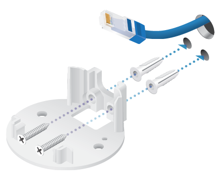
- If the Ethernet cable is coming from the inside of a wall:
- Drill or cut a hole in the wall and feed the Ethernet cable through the opening.
- Pull the Ethernet cable forward and slide it through the opening in the mount.
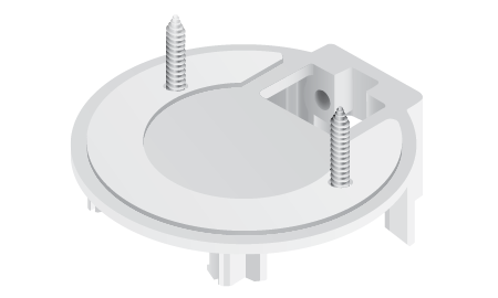
- Use the Screws and Screw Anchors to secure the Flush Mount to the wall.
or
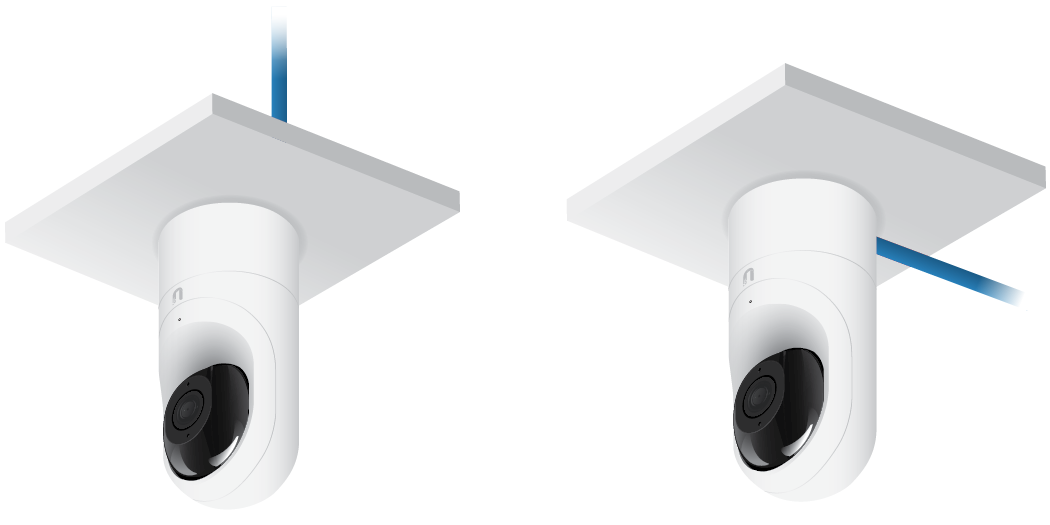
Top Side Down Mounting Vertical Upright Mounting - Connect the Ethernet cable to the Ethernet Port in the base of the camera.
- Attach the camera to the Flush Mount by lining up the notches with the slots in the base of the camera. Press firmly together until the camera is secure.
or
Vertical mounting on ceiling Vertical mounting on a wall
Installation complete.
Horizozntal Surface / Ceiling with Flush Mount
Indoor Wall with Flush Mount
Pole
|
|
Note: If you are mounting the camera outdoors, it must be installed in the upright position to prevent water from getting into the base of the camera. Use the Outdoor Cover for additional protection from moisture. |
|---|
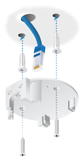
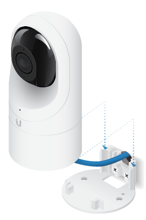
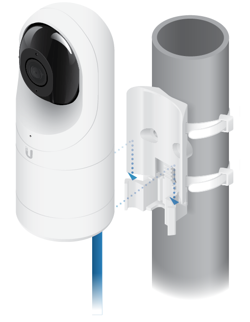
- Attach the Pole Mount to a pole using the included Zip Ties.
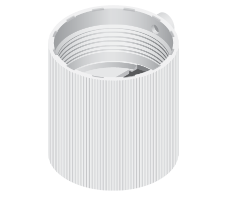
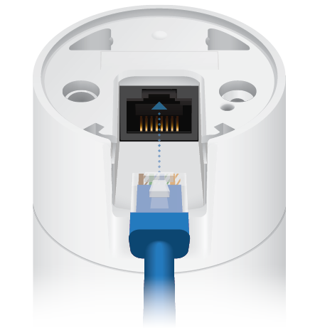
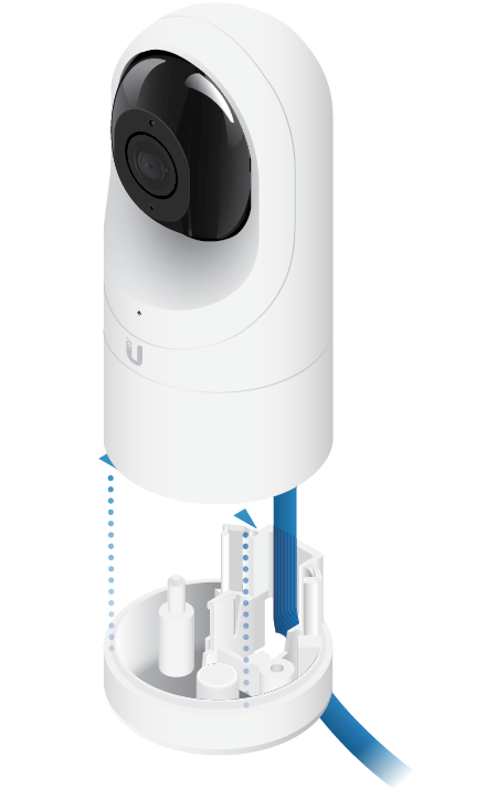
- Insert and pull an Ethernet cable through the back port opening of the Outdoor Cover.
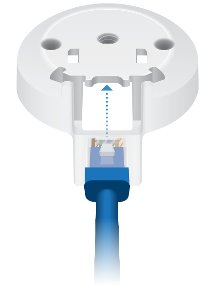
Note: When using the Outdoor Cover, use an Ethernet cable without strain-relief boots on the connector. This will prevent unnecessary tension on the cable ends.
- Connect the Ethernet cable to the Ethernet Port on the G3 Flex camera.
- Attach the camera to the Outdoor Cover by lining up the notches with the slots on the bottom of the camera. Press firmly until the camera snaps on.
- Attach the camera to the Pole Mount:
- Press the camera against the Pole Mount and line up the notches on the mount with the slots on the bottom of the camera.
- Slide the camera down onto the Pole Mount until it is secure.
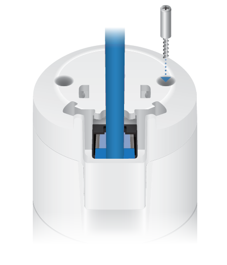
Note: When using the Outdoor Cover, use an Ethernet cable without strain-relief boots on the connector. This will prevent unnecessary tension on the cable ends.
- Use a phillips screwdriver to install the Security Screw through the Outdoor Cover and into the base of the camera. This helps secrure the camera to the mount.
- Adjust the camera to the desired viewing angle by:
- Tilting the lens up or down for vertical adjustment
- Turn the camera body left or right to adjust the angle horizontally
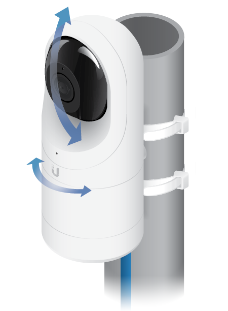
Installation is complete.
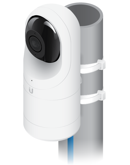
Pole Mount Install
Setting Up UniFi Protect via App
Download and install the UniFi Protect Mobile App to configure the UVC-G3-Flex.
![]()
![]()
|
|
Note: When you first launch UniFi Protect, the app will prompt you to enable Bluetooth and other relevant features necessary to provide the best user experience possible. Please allow these features and permissions to take place for proper app functionality. |
|---|
Specifications
|
UVC-G3-FLEX |
|
|
Dimensions |
Ø 107.5 x 48 x 48 mm (Ø 4.23 x 1.89 x 1.89") |
|---|---|
|
Weight |
170 g (5.99 oz) |
|
Sensor |
1/2.7" 2-Megapixel HDR Sensor |
|
Lens |
EFL 4mm / f2.0 |
|
Viewing Angle with Lens Distortion Correction (LDC) |
|
| LDC Off | 87.4° (H), 47° (V), 104° (D) |
| LDC On | 80° (H), 46° (V), 92° (D) |
|
Night Mode |
IR LEDs with Mechanical ICR Filter |
|
Video Compression |
H.264 |
|
Resolution |
1080p FHD (1920 x 1080) |
|
Maximum Frame Rate |
25 FPS |
|
Image Settings |
Brightness, Contrast, Sharpness, Saturation, Noise Reduction, 50/60 Hz |
|
Microphone |
Yes |
|
Management Interface |
UniFi Protect |
|
Networking Interface |
(1) 10/100 Ethernet Port |
|
Max. Power Consumption |
4W |
|
Power Method |
802.3af PoE |
|
Power Supply |
802.3af PoE Switch Port |
|
Mounting |
Table, Wall (Indoor/Outdoor), Pole |
|
Operating Temperature |
-20 to 50° C |
|
Operating Humidity |
20 to 90% Noncondensing |