Package Contents
 |
|---|
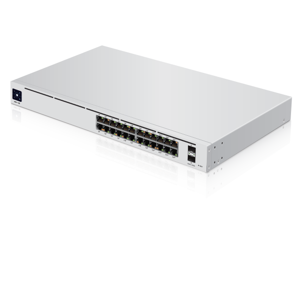
| UniFi Switch |
 |
|---|
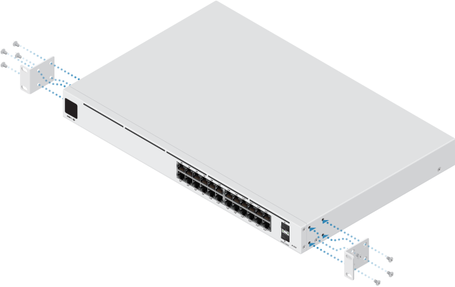
| Rack-Mount Brackets (Qty. 2) |
 |
|---|
| Bracket Screws (Qty. 8) |
 |
|---|
| Mounting Screws (Qty. 4) |
 |
|---|
| Cage Nuts (Qty. 4) |
 |
|---|
| Power Cord |
 |
|---|
| Rubber Feet (Qty. 4) |
System Requirements
- Linux, Mac OS X, or Microsoft Windows 7/8/10
- Java Runtime Environment 1.6 (1.8 or newer recommended)
- Web Browser: Google Chrome (Other browsers may have limited functionality.)
- UniFi Network Application v5.10.x (or newer), available at: ui.com/download/unifi
|
|
IMPORTANT: We strongly recommend using UPS backup and power regulation to prevent equipment damage due to stability issues with local AC power. |
|---|
Hardware Overview


Touchscreen Display |
|
|---|---|
Bootup Animation |
Initializing. |
Steady White |
Factory defaults, waiting for adoption. |
Steady Blue |
Successfully adopted by a network and working properly. |
Location Animation |
This indicates that you clicked Locate in the UniFi Network Application. The Application will also display the location of the device on the map. |

RJ45 PoE LED (Ports 1 - 24) |
|
Off |
No PoE |
Amber |
802.3af/at/bt PoE |

RJ45 Speed/Link/Activity LED (Ports 1 - 24) |
|
Off |
No Link |
Amber |
Link Established at 10/100 Mbps Flashing Indicates Activity |
Green |
Link Established at 1000 Mbps Flashing Indicates Activity |

SFP+ Speed/Link/Activity LED (Ports 25 - 26) |
|
Off |
No Link |
Green |
Link Established at 1 Gbps Flashing Indicates Activity |
White |
Link Established at 10 Gbps Flashing Indicates Activity |

RJ45 (Ports 1 - 16) |
|
RJ45 ports support 10/100/1000 Ethernet connections and 802.3af/at PoE output. |
|

RJ45 (Ports 17 - 24) |
|
RJ45 ports support 10/100/1000 Ethernet connections and 802.3af/at/bt PoE output. |
|

SFP+ (Ports 25 - 26) |
|
Hot-swappable SFP+ ports support 1/10 Gbps connections. |
|

Reset Button |
|
This button serves two functions for the UniFi Switch:
|
|

USP LED |
|
The LED lights up blue when there is an active power connection on the USP DC input. |
|

USP Connect DC Input |
|
This DC input provides redundant power when the UniFi Switch is connected to the UniFi SmartPower Redundant Power System, model USP-RPS, via the USP Cable (not included). If there is an AC power loss or internal power supply failure, the UniFi Switch will draw power from the USP-RPS instead. |
|

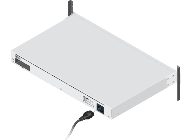
Power Port |
|
Connect the included Power Cord to the Power port. |
|
Installation Requirements
- Phillips screwdriver
- Standard-sized, 19" wide rack with a minimum of 1U height available
- For indoor applications, use Category 5 (or above) UTP cabling approved for indoor use.
- For outdoor applications, shielded Category 5 (or above) cabling should be used for all wired Ethernet connections and should be grounded through the AC ground of the power supply.
We recommend that you protect your networks from harmful outdoor environments and destructive ESD events with industrial-grade, shielded Ethernet cable from Ubiquiti. For more details, visit: ui.com/toughcable
| Note: Although the cabling can be located outdoors, the UniFi Switch itself should be housed inside a protective enclosure. |
|---|
Hardware Installation
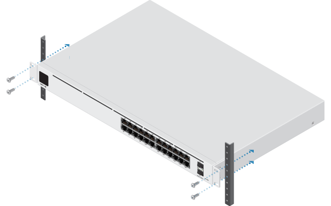
OR
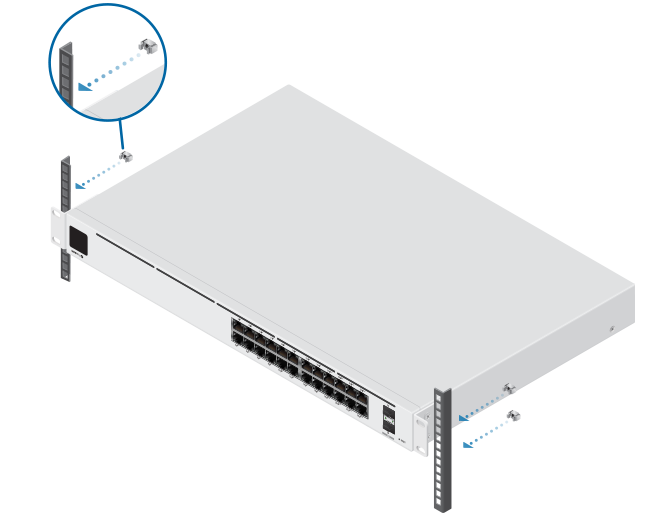
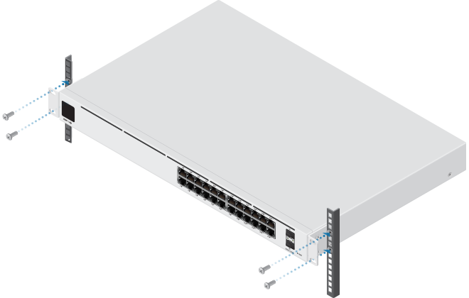
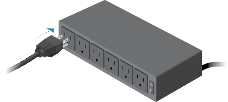
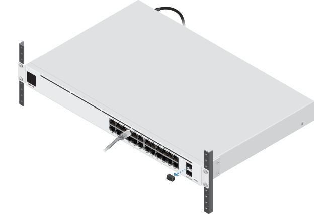
Connecting Power
Connecting Ethernet
![]()
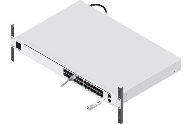
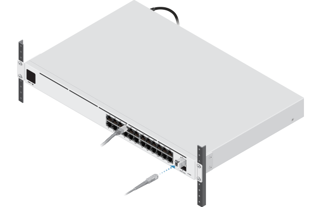
Connecting SFP
For information about compatible fiber SFP modules, visit: ubnt.link/UniFi_SFP_DAC_Compatibility
Specifications
|
USW-Pro-24-POE |
|
|
Dimensions |
442.4 x 285.4 x 43.7 mm |
|---|---|
|
Weight |
4.30 kg (9.48 lb) |
| With Rackmount Brackets | 4.39 kg (9.68 lb) |
|
Interfaces |
|
| Networking | (24) 10/100/1000 RJ45 Ports (2) 1/10G SFP+ Ethernet Ports |
| Management | Ethernet In-Band |
|
Power Method |
|
| Universal Input | 100-240VAC/50-60 Hz |
| USP RPS DC Input | 52VDC, 7.69A; 11.5VDC, 2.61A |
|
Power Supply |
AC/DC, Internal, 450W |
|
Supported Voltage Range |
100 to 240VAC |
|
Max. Power Consumption |
50W |
|
LEDs |
|
| System | Status |
| RJ45 Data Ports | PoE; Speed/Link/Activity |
| SFP+ Data Ports | Link/Activity |
|
ESD/EMP Protection |
Air: ± 16 kV, Contact: ± 12 kV |
|
Shock and Vibration |
ETSI300-019-1.4 Standard |
|
Operating Temperature |
-5 to 40° C (23 to 104° F) |
|
Operating Humidity |
10 to 90% Noncondensing |
|
Certifications |
CE, FCC, IC |
|
Sound Level* |
|
|
25% PoE Load, 25° C Room Temperature |
0.9 dBr |
|---|---|
|
50% PoE Load, 25° C Room Temperature |
7.3 dBr |
|
100% PoE Load, 40° C |
18.8 dBr |
* Background noise level: 27.5 dBa
|
PoE |
|
|
PoE Interfaces |
|
|---|---|
| Ports 1-16 | POE+ IEEE 802.3af/at (pins 1, 2+; 3, 6-) |
| Ports 17-24 | 60W PoE++ IEEE 802.3bt (Pair A 1, 2+; 3, 6-) (Pair B 4 , 5+; 7, 8-) |
|
Max. PoE Wattage per Port by PSE |
|
| 802.3at | 32W |
| 802.3bt | 64W |
|
Voltage Range 802.3af Mode |
44-57V |
|
Voltage Range 802.3at/bt Mode |
50-57V |
