Package Contents
 |
|---|
| UniFi Switch |
 |
|---|
| Mount Brackets (Qty. 2) |
 |
|---|
| Bracket Screws (Qty. 8) |
 |
|---|
| Mounting Screws (Qty. 4) |
 |
|---|
| Screw Anchors (Qty. 4) |
 |
|---|
| Power Adapter |
 |
|---|
| Power Cord |
 |
|---|
| Cable Clip |
System Requirements
- Linux, Mac OS X, or Microsoft Windows 7/8/10
- Java Runtime Environment 1.8 or above recommended
- Web Browser: Google Chrome (Other browsers may have limited functionality)
- UniFi Network Application v5.8.x (or newer), available at: ui.com/download/unifi
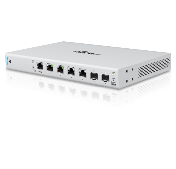
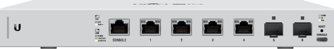
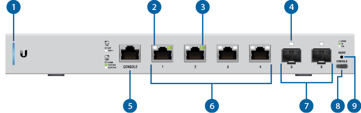
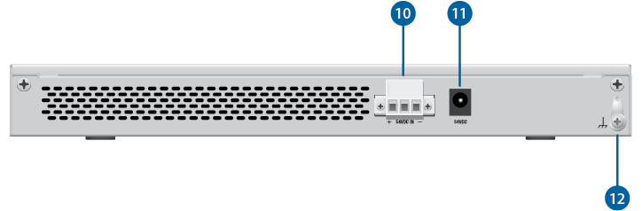
Hardware Overview

System LED |
|||
|---|---|---|---|
Flashing White |
Initializing. |
||
Steady White |
Factory defaults, waiting for adoption. |
||
Alternating White/Blue |
Device is busy; do not touch or unplug it. This usually indicates that a process such as a firmware upgrade is taking place. |
||
Steady Blue |
Successfully adopted by a network and working properly. |
||
Flashing Blue |
This is used to locate a device. When you click Locate in the UniFi Network Application, the System LED will flash blue. The Application will also display the location of the UniFi Switch on the map. |
||

RJ45 PoE LED (Ports 1 - 4) |
|||
Off |
PoE Disabled |
||
White |
802.3af/at/bt PoE |
||

RJ45 Link/Speed/Activity LED (Ports 1 - 4) |
|||
Off |
No Link |
||
Green |
Link Established at 1 Gbps Flashing Indicates Activity |
||
White |
Link Established at 10 Gbps Flashing Indicates Activity |
||

SFP+ Link/Speed/Activity LED (Ports 5 - 6) |
|||
Off |
No Link |
||
Green |
Link Established at 1 Gbps Flashing Indicates Activity |
||
White |
Link Established at 10 Gbps Flashing Indicates Activity |
||

RJ45 Console Port |
|||
RJ45 serial console port for Command Line Interface (CLI) management. Use an RJ45-to-DB9, serial console cable, also known as a rollover cable, to connect the Console port to your computer. Then configure the following settings as needed:
|
|||

RJ45 (Ports 1 - 4) |
|||
RJ45 ports support 100 Mbps or 1/2.5/5/10 Gbps Ethernet connections and 802.3af/at/bt PoE output. |
|||

SFP+ (Ports 5 - 6) |
|||
Hot-swappable SFP+ ports support 1/10 Gbps connections. |
|||

USB Console Port |
|||
USB Type C console port for Command Line Interface (CLI) management. |
|||

Reset Button |
|||
This button serves two functions for the UniFi Switch:
|
|||

DC Input |
|||
Optional DC input for connecting a stand-alone or redundant DC power source (not included) with minimum power: 40W, 44 to 57VDC.
You can use the redundant DC power source as a hot spare; if there is no longer power through the Power port, the UniFi Switch will switch to the DC power source without interrupting its operation. |
|||

Power Port |
|||
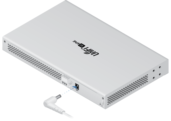
Connect the included Power Adapter to the Power port. |
|||

Ground |
|||
Ancillary grounding point for enhanced ESD protection. |
|||

Hardware Installation
The UniFi Switch can be mounted on a horizontal or vertical surface.
|
|
WARNING: The US-XG-6POE must not be stacked. Do not place it on top of another switch. Do not place anything on top of the US-XG-6POE. |
|---|

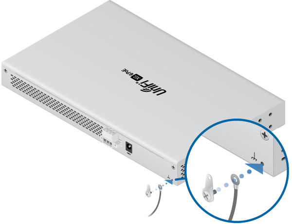
Grounding (Recommended)
The UniFi Switch is grounded through the Power Adapter; however, you can add optional ESD grounding for enhanced ESD protection.
|
|
Note: You also have the option to use the Cable Clip to secure the cord of the Power Adapter. For instructions, proceed to "Using the Cable Clip (Optional)". |
|---|
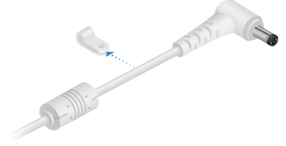
Using the Cable Clip (Optional)


Connecting Power
You have two options:
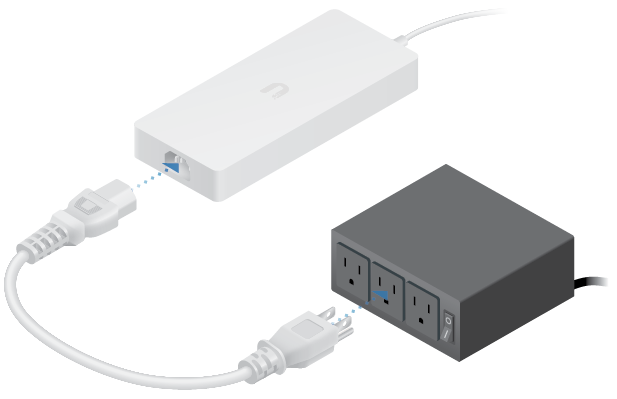
Using the Power Adapter
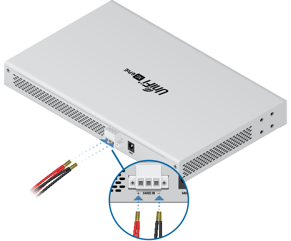
Using the DC Input (Optional)
For stand-alone power or redundant backup, connect a DC power source to the UniFi Switch.
|
|
Note: Only one power source can be used at any one time. With both power sources connected, the input with the highest voltage will be used; the other power source defaults to backup. |
|---|
Wire a DC/DC cable (not included) to the DC Input. Ensure the polarity is correct: red is positive (+) and black is negative (-).
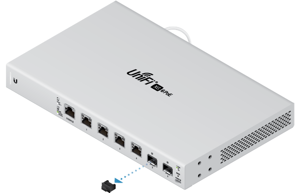
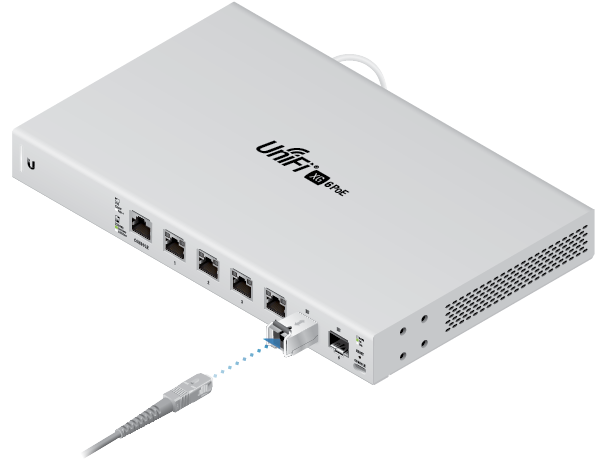
Connecting Ethernet
![]()
Connecting SFP+
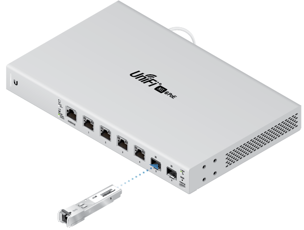
For information about compatible fiber SFP modules, visit: community.ubnt.com/unifi
Specifications
|
US-XG-6POE |
|
|
Dimensions |
165 x 268.1 x 31.8 mm |
|---|---|
|
Weight |
1.3 kg (2.87 lb) |
|
Interfaces |
|
| Networking | (4) 100 Mbps or 1/2.5/5/10G RJ45 Ports (2) 1/10G SFP+ Ethernet Ports |
| Management | Ethernet In-Band (1) RJ45 Serial Port Out-of-Band (1) USB Type C Port Out-of-Band |
|
Power Method |
54VDC, 3.88A Power Adapter (Included) |
|
Power Supply |
External AC/DC Adapter (Included) |
|
Supported Voltage Range |
44 to 57VDC |
|
Max. Power Consumption |
40W |
|
LEDs |
|
| System | Status |
| RJ45 Data Ports | PoE; Speed/Link/Activity |
| SFP+ Data Ports | Link/Activity |
|
ESD/EMP Protection |
Air: ± 18 kV, Contact: ± 12 kV |
|
Shock and Vibration |
ETSI300-019-1.4 Standard |
|
Operating Temperature |
-5 to 45° C (23 to 113° F) |
|
Operating Humidity |
5 to 95% Noncondensing |
|
Certifications |
CE, FCC, IC |
|
PoE |
|
|
PoE Interfaces |
PoE++ IEEE 802.3bt |
|---|---|
|
Max. 802.3bt Wattage per Port by PSE |
60W |
|
Voltage Range 802.3af Mode |
44-57V |
|
Voltage Range 802.3at/bt Mode |
50-57V |