Package Contents
 |
|---|
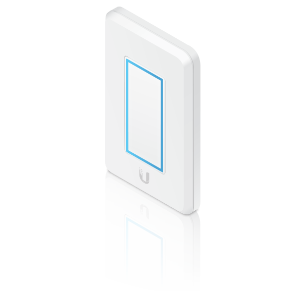
| UniFi Dimmer Switch |
 |
|---|
| Mounting Screws (Qty. 2) |
System Requirements
- An 802.3af-compliant network switch
- UniFi Connect Mobile app
- Mobile device: iOS 10 or Android™ 5.0
- UniFi Connect Application:
- Computer: UniFi Application Server 0.5.0, Ubuntu 16.04 LTS (Xenial Xerus) 64-bit, or Debian 9 64-bit
- Web browser: Google Chrome (Other browsers may have limited functionality.)
Hardware Overview
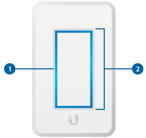

LED |
|
|---|---|
Flashing White |
Initializing. |
Breathing White |
System ready. |
Alternating White/Blue |
Firmware upgrade is taking place. |
Breathing Blue |
Adopted by the Connect Application. |
Flashing Blue |
This is used to locate a UniFi Dimmer Switch. When you click Locate in the UniFi Coonect Application or UniFi Connect Mobile app, the UniFi Dimmer Switch LED will flash. |

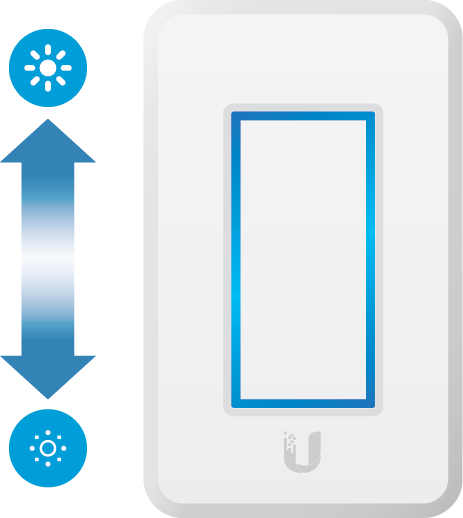
Touch Pad |
|
Once the UniFi Dimmer Switch is paired with the UniFi LED Panel, you can use the UniFi Dimmer Switch’s Touch Pad to turn the LED Panel on and off and to control its brightness:
|
|

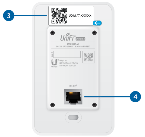
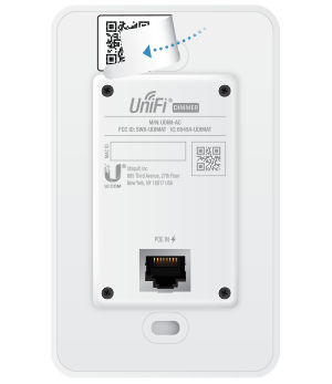
MAC Sticker |
|
Used to scan the MAC address. For details, refer to “Quick Setup”. |
|

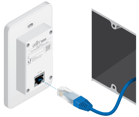
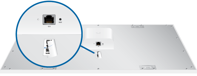
PoE + Data |
|
This 10/100 Ethernet port supports data and 802.3af PoE. Connect this port to a UniFi Switch with PoE that is connected to your LAN and DHCP server. |
|

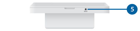
Reset |
|
The Reset button serves two functions:
|
|
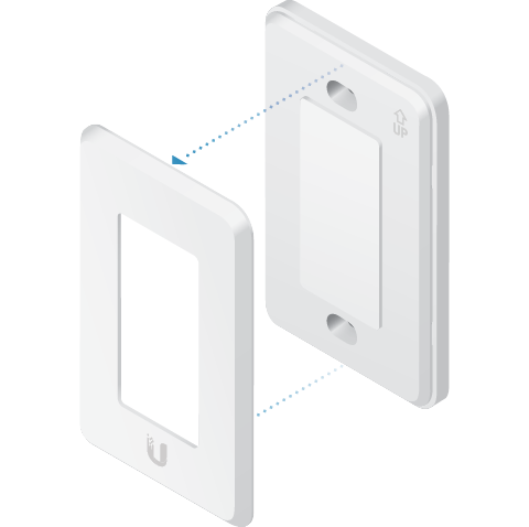
Hardware Installation
An electrical wall box should be pre-installed with an Ethernet cable running from the box to a UniFi Switch with 802.3af PoE.
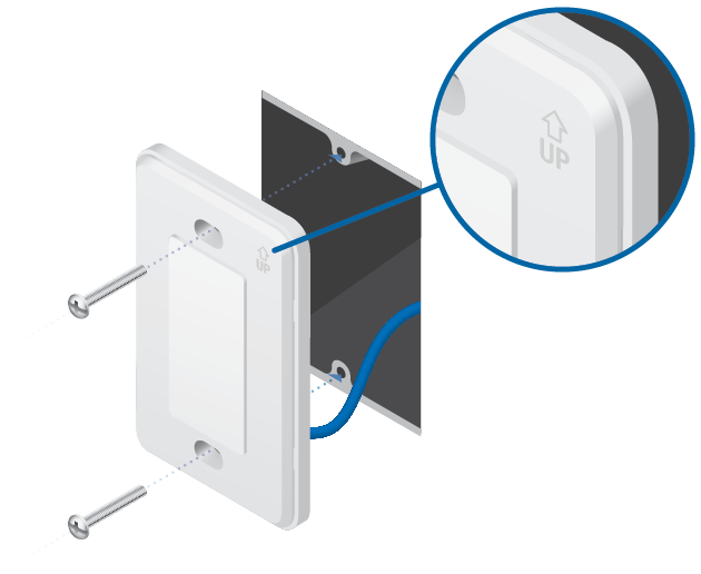
| WARNING: To avoid damage, use ONLY the included Mounting Screws or #6-32x26 truss head machine screws (maximum head diameter: 8 mm). Do NOT over-tighten the screws. |
|---|

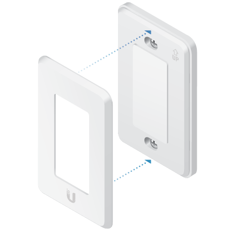
The UniFi Dimmer Switch is Plug and Play; by default, it will be paired automatically with all UniFi LED Panels on the same Layer 2 network.
|
|
Note: For best results:
|
|---|

Quick Setup
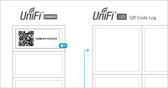
This section describes the Quick Setup procedure for installations with large numbers of UniFi LED Panels and Dimmer Switches. The Quick Setup requires using the UniFi LED app along with a QR Code Log that you create. Each UniFi LED Panel or Dimmer Switch has a removable MAC Sticker on its reverse side; this has a QR code used to scan the device’s MAC address. The Quick Setup consists of these steps:
- Create the QR Code Log
- Install the LED Panels and Dimmer Switches
- Scan the QR codes
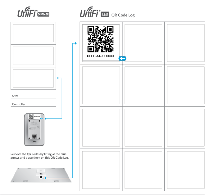
Create the QR Code Log
- Download the QR Code Log template at: ubnt.link/QR-Code-Log
- Print out as many copies as needed (each sheet can log up to 16 LED Panels and 3 Dimmer Switches).
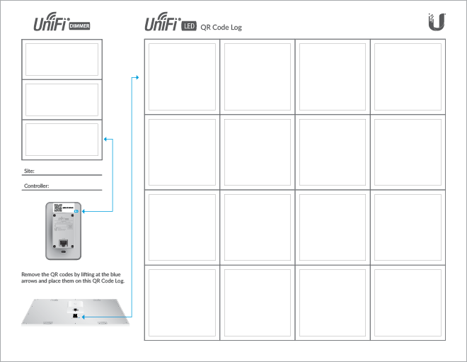
- Fill in the Site (such as “1st Floor Meeting Room”) and OS Console (such as “UniFi Connect Application”) on each sheet.
Install the LED Panels and Dimmer Switches
For each device:
- Install the device as decribed in the Installation section of the device’s Quick Start Guide.
OR
OR
Specifications
|
UDIM-AT |
|
|
Dimensions |
71 x 115 x 25 mm |
|---|---|
|
Weight |
90 g (3.17 oz) |
|
Management Interface |
UniFi Connect Application UniFi Connect Mobile App |
|
Networking Interface |
10/100 Mbps Ethernet Port |
|
Buttons |
Reset |
|
Power Method |
802.3af PoE |
|
Power Supply |
Standard 802.3af PoE |
|
Supported Voltage Range |
48V |
|
Max. Power Consumption |
5W |
|
Operating Temperature |
0 to 40° C (32 to 104° F) |
|
Certifications |
FCC, IC |
Safety Notices
- Read, follow, and keep these instructions.
- Heed all warnings.
- Only use attachments/accessories specified by the manufacturer.
| WARNING: Do not use this product in location that can be submerged by water. |
|---|

| WARNING: Avoid using this product during an electrical storm. There may be a remote risk of electric shock from lightning. |
|---|
Electrical Safety Information
- Compliance is required with respect to voltage, frequency, and current requirements indicated on the manufacturer’s label. Connection to a different power source than those specified may result in improper operation, damage to the equipment or pose a fire hazard if the limitations are not followed.
- There are no operator serviceable parts inside this equipment. Service should be provided only by a qualified service technician.
Limited Warranty
The limited warranty requires the use of arbitration to resolve disputes on an individual basis, and, where applicable, specify arbitration instead of jury trials or class actions.
Compliance
FCC
Changes or modifications not expressly approved by the party responsible for compliance could void the user’s authority to operate the equipment.
This device complies with Part 15 of the FCC Rules. Operation is subject to the following two conditions.
- This device may not cause harmful interference, and
- This device must accept any interference received, including interference that may cause undesired operation.
This equipment has been tested and found to comply with the limits for a Class A digital device, pursuant to part 15 of the FCC Rules. These limits are designed to provide reasonable protection against harmful interference when the equipment is operated in a commercial environment. This equipment generates, uses, and can radiate radio frequency energy and, if not installed and used in accordance with the instruction manual, may cause harmful interference to radio communications. Operations of this equipment in a residential area is likely to cause harmful interference in which case the user will be required to correct the interference at his own expense.
This radio transmitter has been approved by FCC.
ISED Canada
CAN ICES-3(A)/NMB-3(A)
This device complies with ISED Canada licence-exempt RSS standard(s). Operation is subject to the following two conditions:
- This device may not cause interference, and
- This device must accept any interference, including interference that may cause undesired operation of the device.
This radio transmitter has been approved by ISED Canada.
CAN ICES-3(A)/NMB-3(A)
Le présent appareil est conforme aux CNR d’ISDE Canada applicables aux appareils radio exempts de licence. L’exploitation est autorisée aux deux conditions suivantes :
- l’appareil ne doit pas produire de brouillage;
- l’appareil doit accepter tout brouillage radioélectrique subi, même si le brouillage est susceptible d’en compromettre le fonctionnement.
Le présent émetteur radio a été approuvé par ISDE Canada.
IMPORTANT NOTE
Radiation Exposure Statement
- This equipment complies with radiation exposure limits set forth for an uncontrolled environment.
- This equipment should be installed and operated with minimum distance 20 cm between the radiator and your body.
- This transmitter must not be co-located or operating in conjunction with any other antenna or transmitter.
AVIS IMPORTANT
Déclaration sur l’exposition aux rayonnements
- Cet équipement est conforme aux limites prévues pour l’exposition aux rayonnements dans un environnement non contrôlé.
- Lors de l’installation et de la mise en fonctionnement de l’équipement, assurez-vous qu’il y ait une distance minimale de 20 cm entre l’élément rayonnant et vous.
- Cet émetteur ne doit être installé à proximité d’aucune autre antenne ni d’aucun autre émetteur, et ne doit être utilisé conjointement à aucun autre de ces appareils.