Package Contents
 |
|---|
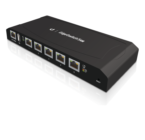
| EdgeSwitch 5XP |
 |
|---|
| Screws (Qty. 2) |
 |
|---|
| Anchors (Qty. 2) |
 |
|---|
| Power Adapter (24V, 2.5A) |
 |
|---|
| Power Cord |
Installation Requirements
- Drill, 6 mm drill bit, and Phillips screwdriver (wall-mounting)
- For outdoor applications, shielded Category 5 (or above) cabling should be used for all wired Ethernet connections and should be grounded through the AC ground of the power supply.
We recommend that you protect your networks from harmful outdoor environments and destructive ESD events with industrial-grade, shielded Ethernet cable from Ubiquiti. For more details, visit ui.com/toughcable
| IMPORTANT: Although the cabling can be located outdoors, the EdgeSwitch itself should be housed inside a protective enclosure. |
|---|

|
|
WARNING: To reduce the risk of fire or electric shock, do not expose this EdgeSwitch to rain or moisture. |
|---|
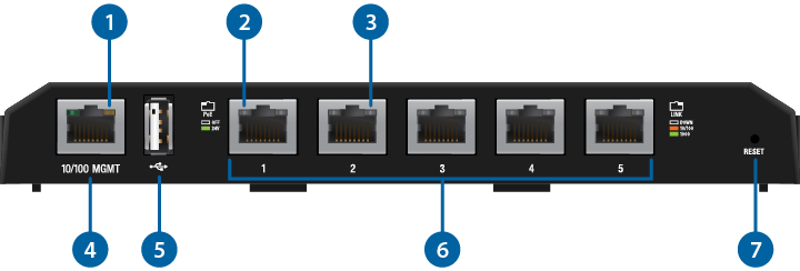
Hardware Overview

Management Power/Link LED |
|
|---|---|
Off |
No Power/No Link |
Amber |
After bootup, the LED indicates power. After an initial link is established, the LED indicates a 10/100 Mbps connection. If the link terminates, the LED turns off until a link is re-established. If the unit reboots, the LED will again indicate power until a link is established. |

RJ45 PoE LED (Ports 1 - 5) |
|
Off |
No Power over Ethernet |
Green |
24V Power over Ethernet |

RJ45 Speed/Link/Act LED (Ports 1 - 5) |
|
Off |
No link |
Amber |
Link established at 10/100 Mbps |
Amber Flashing |
Link activity at 10/100 Mbps |
Green |
Link established at 1000 Mbps |
Green Flashing |
Link activity at 1000 Mbps |

Management Port |
|
10/100 Mbps port used to access the EdgeSwitch Configuration Interface. |
|

USB Port |
|
Reserved for future use. |
|

RJ45 (Ports 1 - 5) |
|
10/100/1000 Mbps ports for switching and PoE (also available for management by default). |
|

Reset Button |
|
To reset to factory defaults, press and hold the Reset button for more than 10 seconds while the unit is powered on. |
|

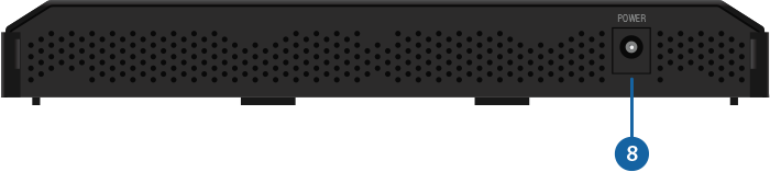
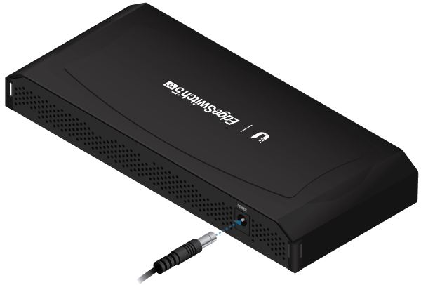
Power |
|
Connect the included Power Adapter to the Power port. |
|
Hardware Installation
Place the EdgeSwitch on a bench top or other flat surface.
|
|
WARNING: FAILURE TO PROVIDE PROPER VENTILATION MAY CAUSE FIRE HAZARD. KEEP AT LEAST 20 MM OF CLEARANCE NEXT TO THE VENTILATION HOLES FOR ADEQUATE AIRFLOW. |
|---|
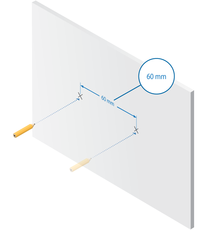
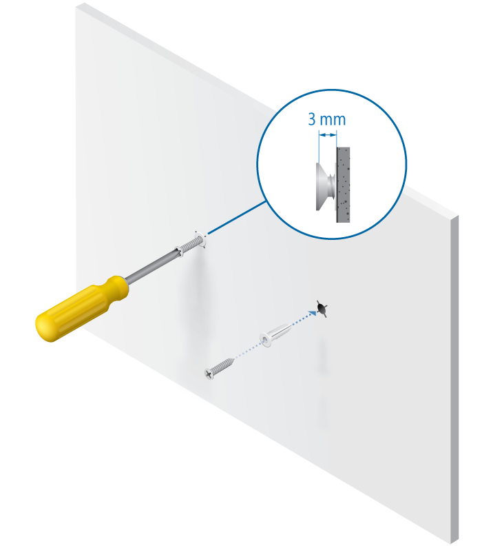
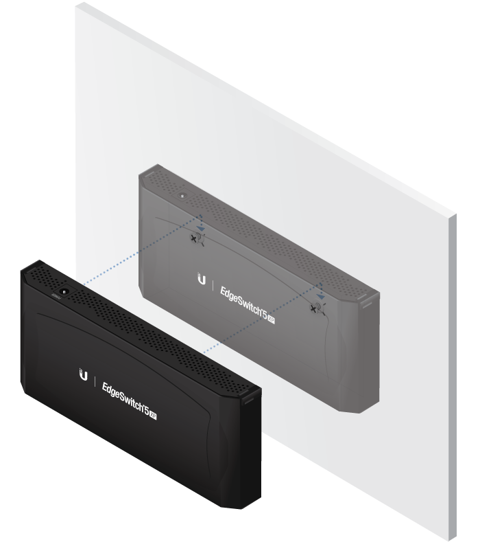
Wall-Mounting

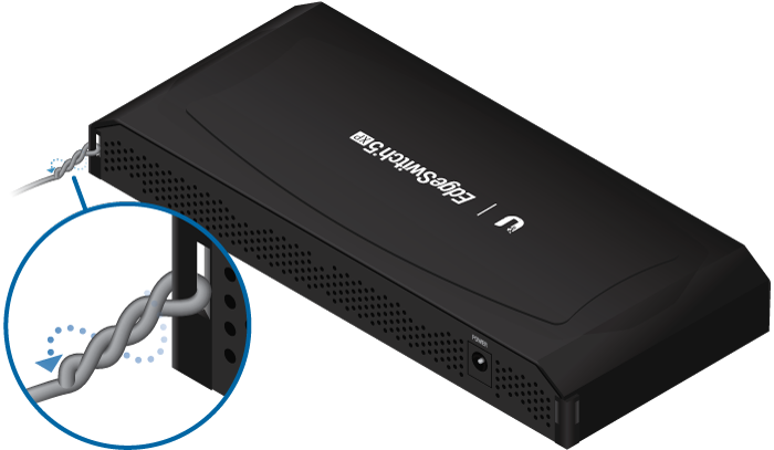
Grounding the EdgeSwitch (Optional)
The EdgeSwitch is grounded through the Power Adapter; however, you can add optional ESD grounding for enhanced ESD protection.
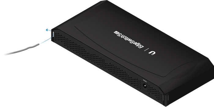
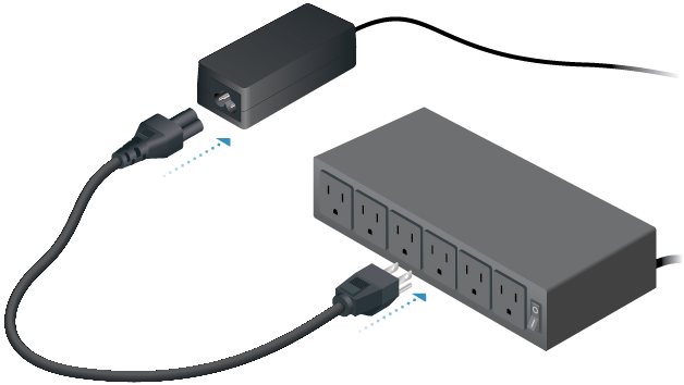
Connecting Power
Connecting Ethernet
|
|
Note: PoE is disabled by default on all numbered ports and is not available on the Management port. To enable PoE on the appropriate ports, use the Ports tab in the Configuration Interface. |
|---|

Accessing the Configuration Interface
Connect to the Configuration Interface:
- Ensure that your computer (or other host machine) is connected to the Management port on the EdgeSwitch.
- Configure the Ethernet adapter on your host system with a static IP address on the 192.168.1.x subnet (e.g., 192.168.1.100).
- Launch your web browser. Type https://192.168.1.20 in the address field. Press enter (PC) or return (Mac).
- Enter ubnt in the Username and Password fields. Click Login.
| Note: By default, you can configure the EdgeSwitch via any port; however, we recommend the Management port. (Access to the Configuration Interface can be limited to the Management port only. You can configure this setting on the Device tab.) |
|---|

The Configuration Interface will appear and allow you to customize your settings. You can enable PoE on the Ports tab.
You can also manage your device using the Ubiquiti Internet Service Provider. UISP™ lets you configure, monitor, upgrade, and back up your devices using a single application.
Specifications
|
ES-5XP |
|
|
Dimensions |
197 x 87.5 x 27.3 mm (7.76 x 7.28 x 1.61") |
|---|---|
|
Weight |
250 g (8.82 oz) |
|
Power Input |
24VDC, 2.5A Power Adapter (Included) |
|
Max. Power Consumption |
60W |
|
PoE Out Voltage Range |
22-24VDC |
|
Max. PoE Wattage Per Data Port |
11.5W |
|
ESD Rating |
±24 kV Air/Contact |
|
PoE Method |
Passive |
|
Button |
Reset |
|
USB Port |
2.0 Type A (Reserved for Future Use) |
|
Processor |
MIPS 24K, 400 MHz |
|
System Memory |
64 MB |
|
Code Storage |
8 MB |
|
PoE Configurable Per Port |
|
| Management Port | N/A |
| Data Ports | Off/24V |
|
LEDs Per Port |
|
| Management Port | Power/Link |
| Data Ports | PoE, Speed/Link/Activity |
|
Networking Interfaces |
|
| Management Port | (1) 10/100 Ethernet Port |
| Data Ports | (5) 10/100/1000 Ethernet Ports |
|
Operating Temperature |
-25 to 55° C (-13 to 131° F) |
|
Operating Humidity |
90% Noncondensing |
|
Certifications |
CE, FCC, IC |