Package Contents
 |
|---|
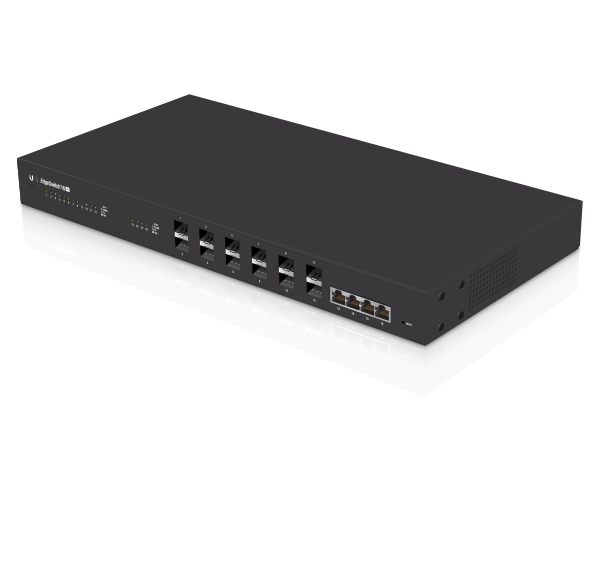
| EdgeSwitch |
 |
|---|
| Rack-Mount Brackets (Qty. 2) |
 |
|---|
| Bracket Screws (Qty. 8) |
 |
|---|
| Mounting Screws (Qty. 4) |
 |
|---|
| Cage Nuts (Qty. 4) |
 |
|---|
| Power Cord |
Installation Requirements
- Phillips screwdriver (for rack- or wall-mounting)
- Standard-sized, 19" wide rack with a minimum of 1U height available (for rack-mounting)
- Use compatible fiber SFP+ modules with the appropriate fiber optic cabling. For information about compatible fiber SFP+ modules, visit: ubnt.link/SFP_DAC_Compatibility
- For indoor applications, use Category 6A (or above) UTP cabling approved for indoor use.
- For outdoor applications, shielded Category 6A (or above) cabling should be used for all wired Ethernet connections and should be grounded through the AC ground of the power supply.
We recommend that you protect your networks from harmful outdoor environments and destructive ESD events with industrial-grade, shielded Ethernet cable from Ubiquiti. For more details, visit: ui.com/toughcable
| Note: Although the cabling can be located outdoors, the EdgeSwitch itself should be housed inside a protective enclosure. |
|---|

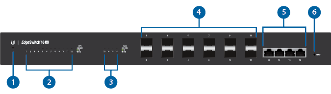
Hardware Overview
|
|
Note: The System LED functionality has been updated with firmware v1.8.0. We recommend that you update the EdgeSwitch to the latest firmware. |
|---|

System LED |
|||
|---|---|---|---|
|
Flashing White |
Bootup in progress. |
||
|
White |
Ready for use, not connected to Ubiquiti Internet Service Provider (UISP™). |
||
|
Blue |
Ready for use, connected to UISP. |
||
|
Steady Blue with Occasional Flashing |
Ready for use, unable to connect to UISP, check connection to UISP server. |
||
|
Quickly Flashing Blue |
Used to locate a device in UISP. |
||
|
Alternating |
Firmware upgrade in progress. |
||

SFP+ Speed/Link/Act LED (Ports 1 - 12) |
|||
Off |
No Link |
||
Green |
Link Established at 1 Gbps Flashing Indicates Activity |
||
White |
Link Established at 10 Gbps Flashing Indicates Activity |
||

RJ45 Speed/Link/Act LED (Ports 13 - 16) |
|||
Off |
No Link |
||
Green |
Link Established at 1 Gbps Flashing Indicates Activity |
||
White |
Link Established at 10 Gbps Flashing Indicates Activity |
||

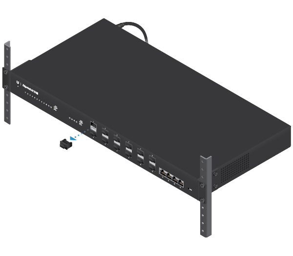
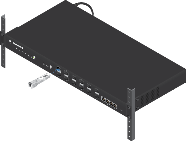
SFP+ (Ports 1 - 12) |
|||
Hot-swappable SFP+ ports support 1 Gbps and 10 Gbps connections. |
|||

RJ45 (Ports 13 - 16) |
|||
RJ45 ports support 1 Gbps and 10 Gbps Ethernet connections. |
|||

Reset Button |
|||
There are two methods to reset the EdgeSwitch to factory defaults: Runtime Reset (Recommended) The EdgeSwitch should be running after bootup is complete, and the System LED is white. Press and hold the Reset button. The EdgeSwitch will reboot, and the System LED becomes blue after three seconds. Continue to hold the Reset button for about 15 seconds until the System LED flashes blue for two seconds. This indicates that the EdgeSwitch has reset to its factory defaults. Power-on Reset
|
|||

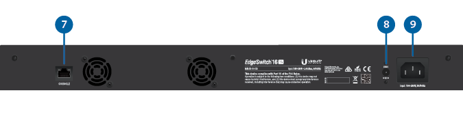
Console |
|||
RJ45 serial console port for Command Line Interface (CLI) management. Use an RJ45-to-DB9, serial console cable, also known as a rollover cable, to connect the Console port to your computer. Then configure the following settings as needed:
|
|||

DC Input |
|||
The 25VDC input can connect a redundant or stand-alone DC power source (not included) with minimum power: 56W, 25 to 16V, and 2.5 mm DC power inline connector.
|
|||

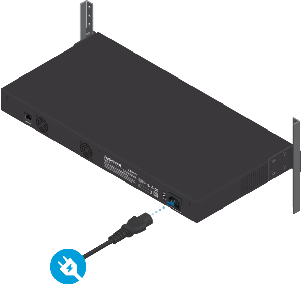
Power |
|||
Connect the included Power Cord to the Power port. |
|||
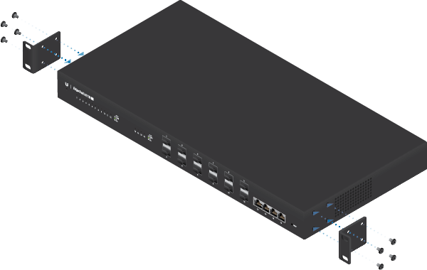
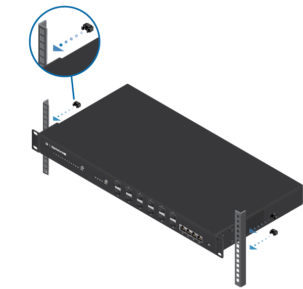
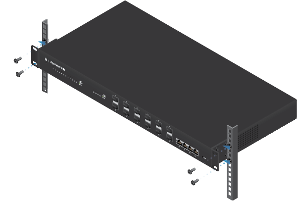
Hardware Installation
Mounting in a Rack (Optional)
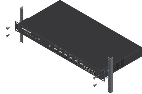
OR
Connecting Power
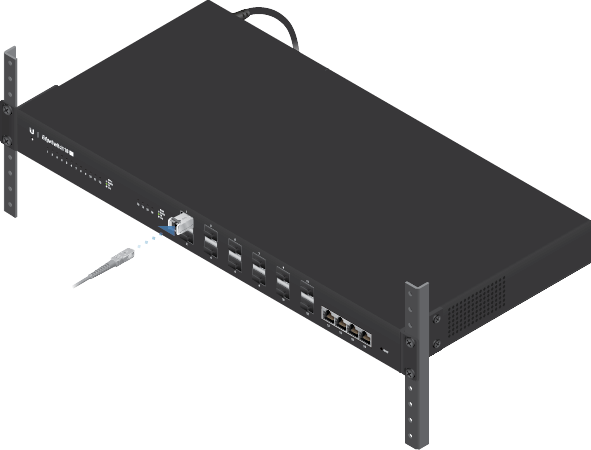
Connecting SFP+
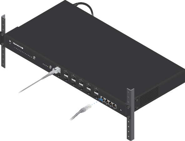
Connecting RJ45
Accessing the Configuration Interface
The EdgeSwitch is set to DHCP by default, so it will try to automatically obtain an IP address. If that fails, then it will use the default fallback IP address, 192.168.1.2. Proceed to the appropriate section, DHCP or “Fallback IP Address”:
DHCP
Use one of the following methods:
- Set up the DHCP server to provide a specific IP address to the EdgeSwitch based on its MAC address (on the label).
- Let the EdgeSwitch obtain an IP address and then check the DHCP server to see which IP address was assigned.
To log in, follow these steps:
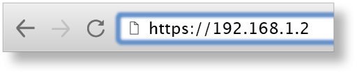
- Launch your web browser. Type the appropriate IP address in the address field. Press enter (PC) or return (Mac).
- Enter ubnt in the Username and Password fields. Click Sign In.
The EdgeSwitch Configuration Interface will appear. Customize additional settings as needed. For more information, refer to the EdgeSwitch documentation, which is available at ui.com/download/edgemax
Fallback IP Address
- Ensure that your computer (or other host system) is connected to the EdgeSwitch.
- Configure the Ethernet adapter on your host system with a static IP address on the 192.168.1.x subnet.
- Launch your web browser. Type the appropriate IP address in the address field (192.168.1.2 is the default fallback IP address). Press enter (PC) or return (Mac).
- Enter ubnt in the Username and Password fields. Click Sign In.
- The EdgeSwitch Configuration Interface will appear. Click the System Settings tab.
- Change the IP Address to a unique IP address. Click Apply.
|
|
Note: If you change the IP settings, then the session will be cut off, and you will need to reconnect to the EdgeSwitch using the new IP address. |
|---|
Customize additional settings as needed. For more information, refer to the EdgeSwitch documentation, which is available at ui.com/download/edgemax
UISP Management
You can manage your device using UISP, which lets you configure, monitor, upgrade, and back up your devices using a single application. Get started at uisp.ui.com
Specifications
|
ES-16-XG |
|
|
Dimensions |
443 x 221 x 43 mm (17.44 x 8.70 x 1.69") |
|---|---|
|
Weight |
2.62 kg (5.78 lb) |
| With Mount Brackets | 2.71 kg (5.97 lb) |
|
Total Non-Blocking Line Rate |
160 Gbps |
|
Max. DC Power Consumption |
36W |
|
Power Method |
|
| AC | 100-240VAC/50-60 Hz, Universal Input |
| DC | DC 56W, 25 to 16V, with 2.5 mm DC Power Inline Connector |
|
Power Supply |
AC/DC, Internal, 56W DC |
|
Supported Voltage Range |
100 to 240VAC 25 to 16VDC |
|
Rack-Mount |
Yes, 1U High |
|
LEDs Per Port |
|
| SFP+ Data Ports | Speed/Link/Activity |
| RJ45 Data Ports | Speed/Link/Activity |
|
Interfaces |
|
| Networking Interfaces | (12) 1/10 Gbps SFP+ Ethernet Ports (4) 1/10 Gbps RJ45 Ethernet Ports |
| Management Interface | (1) RJ45 Serial Port, Ethernet In-Band |
|
ESD/EMP Protection |
Air: ± 24 kV, Contact: ± 24 kV |
|
Shock and Vibration |
ETSI300-019-1.4 Standard |
|
Operating Temperature |
-5 to 40° C (23 to 104° F) |
|
Operating Humidity |
5 to 95% Noncondensing |
|
Certifications |
CE, FCC, IC |