Package Contents
 |
|---|
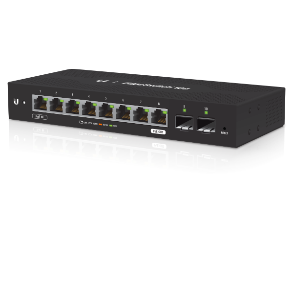
| EdgeSwitch 10X |
 |
|---|
| Wall Mount Screws (Qty. 2) |
 |
|---|
| Wall Mount Anchors (Qty. 2) |
 |
|---|
| Ground Screw |
 |
|---|
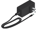
| Power Adapter (24V, 1A) |
 |
|---|
| Cable Clip |
Installation Requirements
- Wall-mounting (optional)
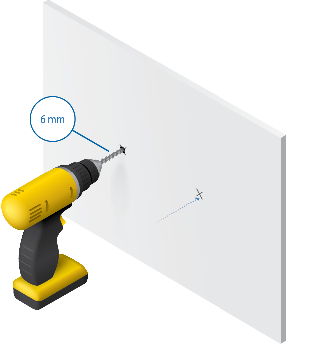
- Drill with 6 mm drill bit
- Phillips screwdriver
- For indoor applications, use Category 5 (or above) UTP cabling approved for indoor use.
- For outdoor applications, shielded Category 5 (or above) cabling should be used for all wired Ethernet connections and should be grounded through the AC ground of the power supply.
We recommend that you protect your networks from harmful outdoor environments and destructive ESD events with industrial-grade, shielded Ethernet cable from Ubiquiti. For more details, visit: ui.com/toughcable
| Note: Although the cabling can be located outdoors, the EdgeSwitch itself should be housed inside a protective enclosure. |
|---|

Hardware Overview
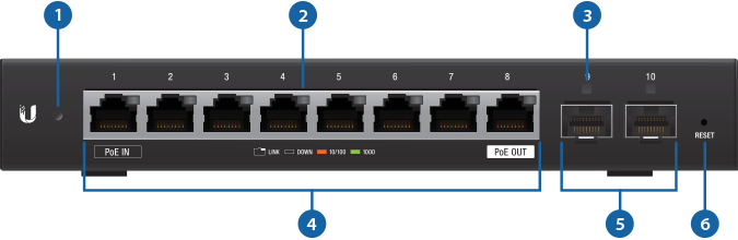

System LED |
|
|---|---|
|
Flashing White |
Bootup in Progress |
|
White |
Ready for Use Not Connected to Ubiquiti Internet Service Provider (UISP™) |
|
Blue |
Ready for Use Connected to UISP |
|
Steady Blue with Occasional Flashing |
Ready for Use Unable to Connect to UISP |
|
Quickly Flashing Blue |
Used to Locate a Device in UISP |
|
Alternating Blue/White |
Firmware Upgrade in Progress |

RJ45 Speed/Link/Activity LED (Ports 1 - 8) |
|
|
Off |
No Link |
|
Amber |
Link Established at 10/100 Mbps Flashing Indicates Activity |
|
Green |
Link Established at 1000 Mbps Flashing Indicates Activity |

SFP Link/Activity LED (Ports 9 - 10) |
|
|
Off |
No Link |
|
Green |
Link Established at 1 Gbps Flashing Indicates Activity |

RJ45 (Ports 1 - 8) |
|
RJ45 ports support 10/100/1000 Ethernet connections.
|
|

SFP (Ports 9 - 10) |
|
Hot-swappable SFP ports support 1 Gbps connections. If you use a copper Ethernet module (example: UF-RJ45-1G), power off the EdgeSwitch before insertion; otherwise there may be a device reboot. |
|

Reset Button |
|
To reset to factory defaults:
|
|

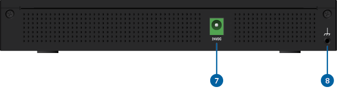
Power |
|
Connect the included Power Adapter to the Power port. |
|

Grounding Point |
|
Ground bonding point for an optional ground wire. |
|
Hardware Installation
The optional EdgeRouter™ Rackmount Kit, model ER-RMKIT, is sold separately.
|
|
WARNING: The EdgeSwitch ES-10X must not be stacked. Do not place it on top of another switch. Do not place anything on top of the ES-10X. |
|---|

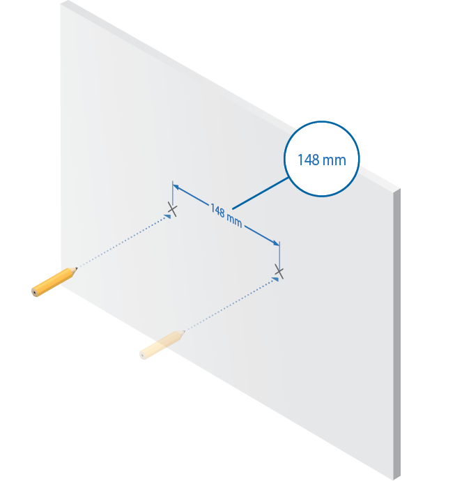
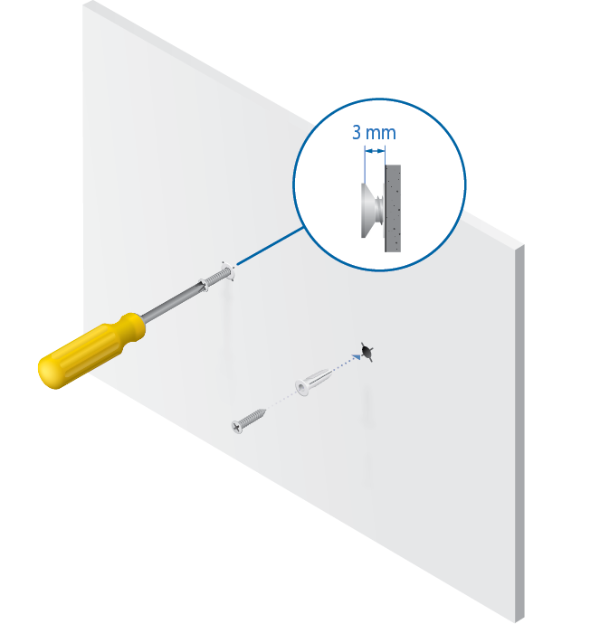
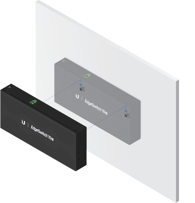
Wall Mounting
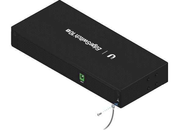
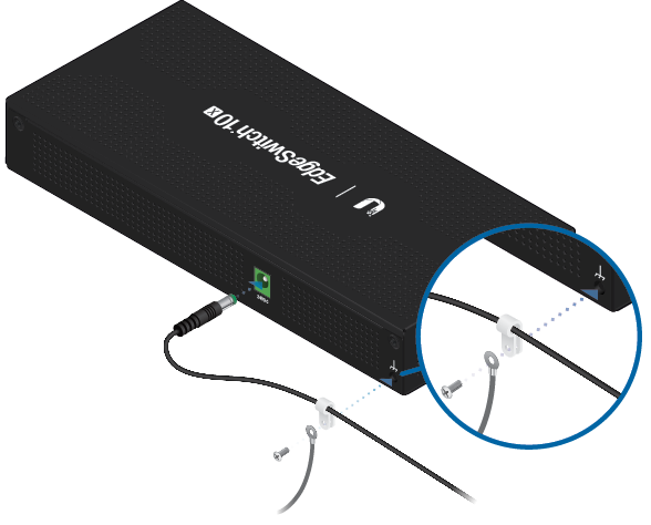
Grounding the EdgeSwitch (Recommended)
The Power Adapter grounds the device; however, you can add optional ESD grounding for enhanced ESD protection (ground wire not included).
Optional
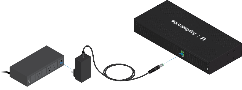
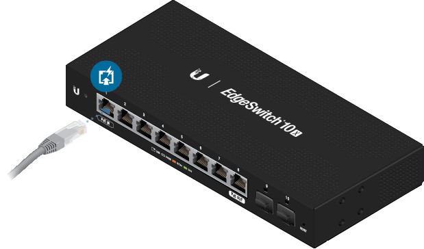
Connecting Power
|
|
Note: Only one power source can be used at any one time. With both power sources connected, the input with the highest voltage will be used; the other power source defaults to backup. |
|---|
OR
Connecting Ethernet
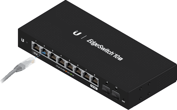
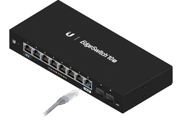
|
|
WARNING: Before enabling PoE passthrough, ensure that the connected PoE device supports 24V Passive PoE. |
|---|
Using SFP Ports
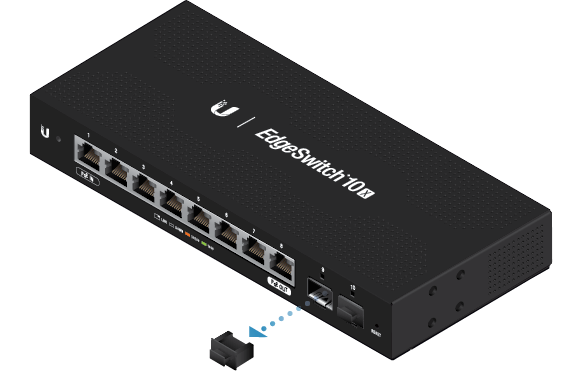
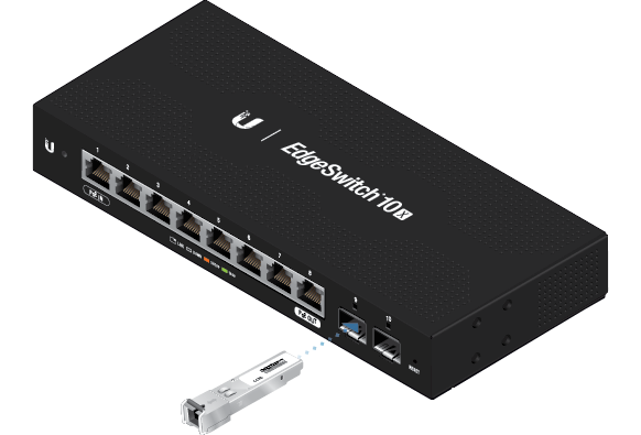
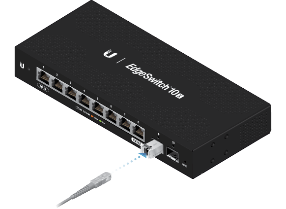
For information about compatible fiber SFP modules, visit: ubnt.link/SFP_DAC_Compatibility
Accessing the Configuration Interface
The device is set to DHCP by default, so it will try to automatically obtain an IP address. If that fails, then it will use the default fallback IP address, 192.168.1.20. Proceed to the appropriate section, DHCP or “Fallback IP Address”:
DHCP
Use one of the following methods:
- Set up the DHCP server to provide a specific IP address to the device based on its MAC address (on the label).
- Let the device obtain an IP address and then check the DHCP server to see which IP address was assigned.
To log in, follow these steps:
- Launch your web browser. Type the appropriate IP address in the address field. Press enter (PC) or return (Mac).
- Enter ubnt in the Username and Password fields. Click Sign In.
The EdgeSwitch Configuration Interface will appear. Customize additional settings as needed. For 24V Passive PoE configuration, refer to “Configuring PoE Settings”. For more information, refer to the EdgeSwitch documentation, which is available at ui.com/download/edgemax
Fallback IP Address
- Ensure that your computer (or other host system) is connected to the device.
- Configure the Ethernet adapter on your host system with a static IP address on the 192.168.1.x subnet.
- Launch your web browser. Type the appropriate IP address in the address field (192.168.1.20 is the default fallback IP address). Press enter (PC) or return (Mac).
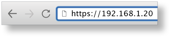
- Enter ubnt in the Username and Password fields. Click Sign In.
- The EdgeSwitch Configuration Interface will appear. Click the System Settings tab.
- Change the IP Address to a unique IP address. Click Apply.
|
|
Note: If you change the IP settings, then the session will be cut off, and you will need to reconnect to the device using the new IP address. |
|---|
Customize additional settings as needed. For 24V Passive PoE configuration, refer to “Configuring PoE Settings”. For more information, refer to the EdgeSwitch documentation, which is available at ui.com/download/edgemax
Configuring PoE Settings
The PoE setting for port 8 is set to Off by default.
|
|
WARNING: Before activating PoE, ensure that the connected device supports passive PoE and the supplied voltage. |
|---|
On the Dashboard tab, click the PoE setting of port 8. Then select 24V.
UISP Management
You can manage your device using UISP, which lets you configure, monitor, upgrade, and back up your devices using a single application. Get started at uisp.ui.com
Specifications
|
ES-10X |
|
|
Dimensions |
207 x 31.1 x 90 mm (8.15 x 1.22 x 3.54") |
|---|---|
|
Weight |
500 g (1.10 lb) |
|
Total Non-Blocking Throughput |
10 Gbps |
|
Switching Capacity |
20 Gbps |
|
Forwarding Rate |
14.88 Mpps |
|
Max. Power Consumption |
8W |
|
Power Method |
24VDC, 1A or |
|
Supported Voltage Range |
9 -30VDC |
|
Power Supply |
24VDC, 1A Power Adapter (Included) or |
|
LEDs |
|
| System | Status |
| RJ45 Data Ports | Link/Speed/Activity |
| SFP Data Ports | Link/Activity |
|
Networking Interfaces |
(8) 10/100/1000 Mbps RJ45 Ports (2) 1 Gbps SFP Ports |
|
Management Interface |
Ethernet In-Band |
|
Certifications |
CE, FCC, IC |
|
ESD/EMP Protection |
Air: ± 24 kV, Contact: ± 24 kV |
|
Operating Temperature |
-10 to 50° C (14 to 122° F) |
|
Operating Humidity |
5 to 95% Noncondensing |
|
Shock and Vibration |
ETSI300-019-1.4 Standard |
|
PoE (Port 8) |
|
|
PoE Interface |
24VDC Passive PoE (Pins 4, 5+; 7, 8-) |
|---|---|
|
Max. Passive PoE Wattage per Port |
15W |
|
24V Passive PoE Voltage Range |
24V |