Package Contents
 |
|---|
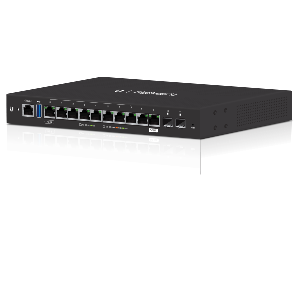
| EdgeRouter ER-12 |
 |
|---|
| Wall Mount Screws (Qty. 2) |
 |
|---|
| Wall Mount Anchors (Qty. 2) |
 |
|---|
| Ground Screw |
 |
|---|
| Power Adapter (24V, 1A) |
 |
|---|
| Cable Clip |
Installation Requirements
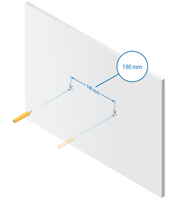
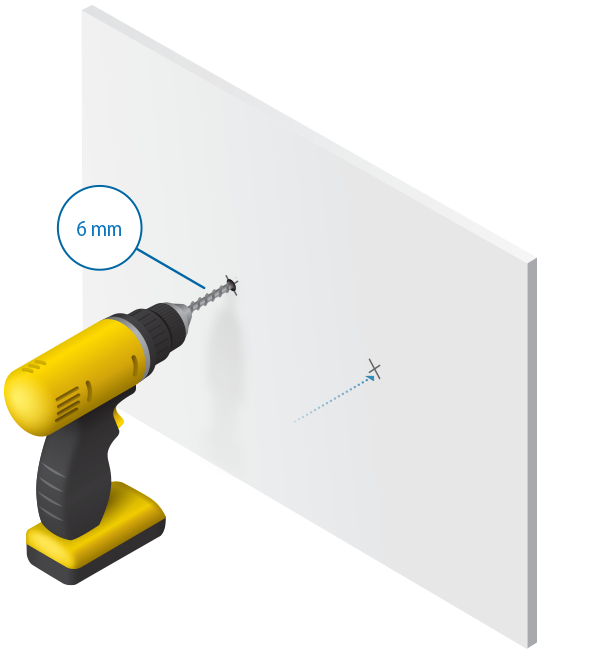
- Wall-mounting (optional)
- Drill with 6 mm drill bit
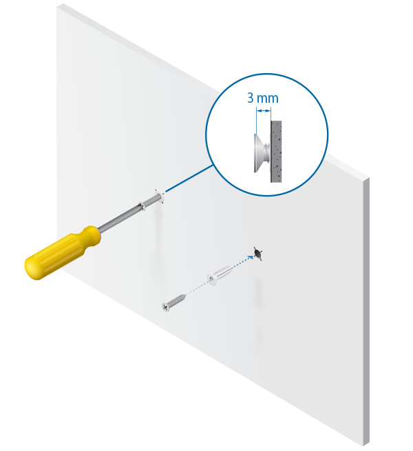
- Phillips screwdriver
- For indoor applications, use Category 5 (or above) UTP cabling approved for indoor use.
- For outdoor applications, shielded Category 5 (or above) cabling should be used for all wired Ethernet connections and should be grounded through the AC ground of the power supply.
We recommend that you protect your networks from harmful outdoor environments and destructive ESD events with industrial-grade, shielded Ethernet cable from Ubiquiti. For more details, visit: ui.com/toughcable
|
|
Note: Although the cabling can be located outdoors, the EdgeRouter itself should be housed inside a protective enclosure. |
|---|

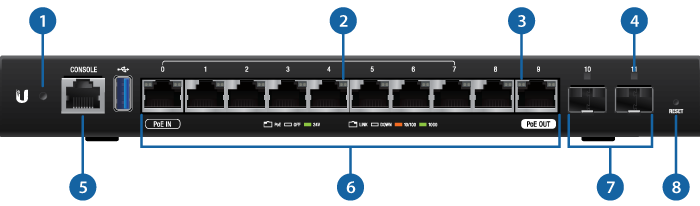
Hardware Overview
|
|
Note: The System LED functionality has been updated with firmware v1.10.7. We recommend that you update the EdgeRouter to the latest firmware. |
|---|
 System LED |
|
|---|---|
Flashing White |
Bootup in progress. |
White |
Ready for use, not connected to Ubiquiti Internet Service Provider (UISP™). |
Blue |
Ready for use, connected to UISP. |
Steady Blue with Occasional Flashing |
Ready for use, unable to connect to UISP, check connection to UISP server. |
Quickly Flashing Blue |
Used to locate a device in UISP. |
Alternating Blue/White |
Firmware upgrade in progress. |
 RJ45 Speed/Link/Act LED (Ports 0 - 9) |
|
|
Off |
No Link |
|
Amber |
Link Established at 10/100 Mbps |
|
Amber Flashing |
Link Activity at 10/100 Mbps |
|
Green |
Link Established at 1000 Mbps |
|
Green Flashing |
Link Activity at 1000 Mbps |
 PoE LED |
|
|
Off |
No PoE |
|
Green |
24V 2-Pair Passive PoE Output |
 SFP Link/Act LED (Ports 10 - 11) |
|
|
Off |
No Link |
|
Green |
Link Established at 1 Gbps |
|
Green Flashing |
Link Activity at 1 Gbps |
 |
|
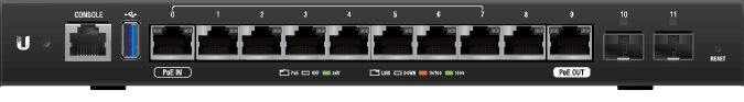
RJ45 serial console port for Command Line Interface (CLI) management. |
|
 RJ45 (Ports 0 - 9) |
|
All RJ45 ports can be used for routing and support 10/100/1000 Mbps Ethernet connections. Ports 0 - 7 can be configured for switching functions using the EdgeOS Configuration Interface. Port 0 supports 24V Passive PoE In and port 9 supports optional Passive PoE Out (disabled by default). |
|
 SFP (Ports 10 - 11) |
|
SFP routing ports are hot-swappable and support Gigabit fiber SFP modules. |
|
 Reset Button |
|
Click here to learn how to reset an EdgeRouter to factory defaults. |
|
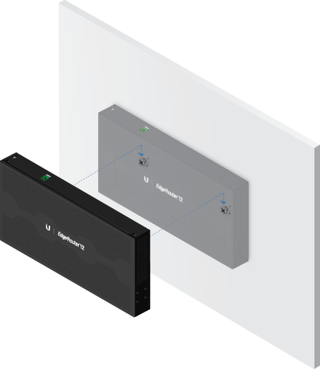
Wall Mounting
Grounding (Recommended)
The Power Adapter grounds the device; however, you can add optional ESD grounding for enhanced ESD protection.
- Attach the Ground Screw to secure a ground wire (not included) to the Grounding Point.
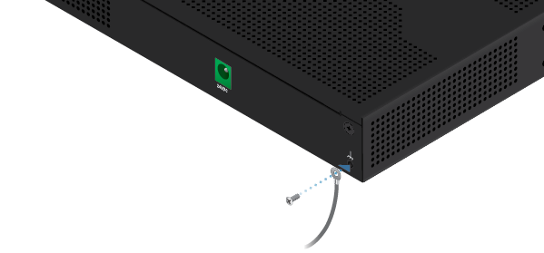
- Optional: To secure the Power Adapter cord, insert it into the Cable Clip and secure the Cable Clip using the Ground Screw.
- Secure the other end of the ground wire to a grounding block.
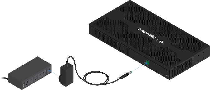
Connecting Power
Connect the Power Adapter to the Power port and a power outlet.
Using SFP Ports
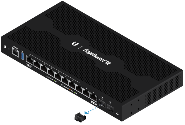
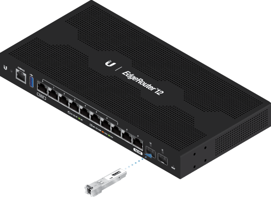
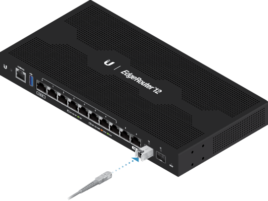
For information about compatible fiber SFP modules, visit:
ubnt.link/SFP_DAC_Compatibility
Accessing the EdgeOS Configuration Interface
The EdgeOS® configuration interface can be accessed via DHCP or static IP address assignment. By default, eth1 is set up as a DHCP client, while eth0 is assigned a static IP address of 192.168.1.1. To configure the EdgeRouter, proceed to the appropriate section: DHCP or “Static IP Address”.
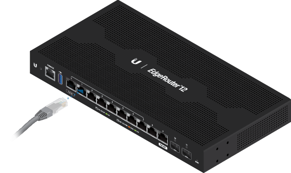
DHCP
- Connect an Ethernet cable from eth1 on the EdgeRouter to a LAN segment that has an existing DHCP server.
- To check the IP address of the EdgeRouter, use one of the following methods:
- Set up the DHCP server to provide a specific IP address to the EdgeRouter based on its MAC address (on the label).
- Let the EdgeRouter obtain an IP address and then check the DHCP server to see which IP address was assigned.
- Launch your web browser. Enter the appropriate IP address in the address field. Press enter (PC) or return (Mac).
- Enter ubnt in the Username and Password fields. Read the Ubiquiti License Agreement, and check the box next to I agree to the terms of this License Agreement to accept it. Click Login.
The EdgeOS Configuration Interface will appear, allowing you to customize your settings as needed. For more information, refer to the EdgeOS User Guide, which is available at ui.com/download/edgemax
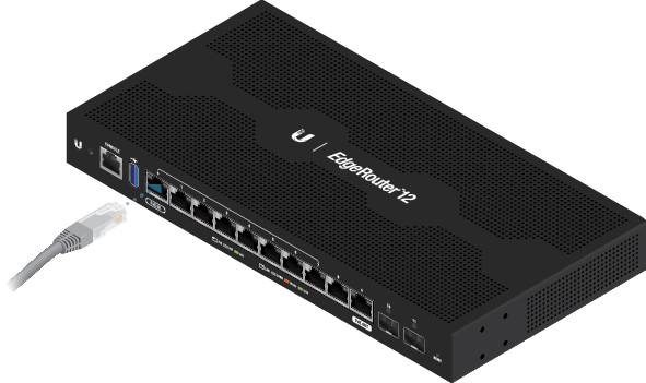
Static IP Address
- Connect an Ethernet cable from the Ethernet port on your computer to the port labeled eth0 on the EdgeRouter.
- Configure the Ethernet adapter on your host system with a static IP address on the 192.168.1.x subnet.
- Launch your web browser. Type https://192.168.1.1 in the address field. Press enter (PC) or return (Mac).
- Enter ubnt in the Username and Password fields. Read the Ubiquiti License Agreement, and check the box next to I agree to the terms of this License Agreement to accept it. Click Login.
The EdgeOS Configuration Interface will appear, allowing you to customize your settings as needed. For more information, refer to the EdgeOS User Guide, which is available at
ui.com/download/edgemax
UISP Management
You can manage your device using UISP, which lets you configure, monitor, upgrade, and back up your devices using a single application. Get started at uisp.ui.com
Specifications
|
ER-12 |
|
|
Dimensions |
268.1 x 136.5 x 31.1 mm |
|---|---|
|
Weight |
700 g (1.54 lb) |
|
Max. Power Consumption |
20W (Excludes PoE Output) |
|
Power Method |
External AC/DC Power Adapter, 24W (24V, 1A) (Included) |
|
Power Supply |
External AC/DC Adapter |
|
Passive PoE |
|
| Voltage Range | DC/PoE Passthrough |
| Max. Wattage per Port | 20W (24V) |
|
Supported Voltage Range |
9 - 30VDC |
|
Button |
Reset |
|
LEDs |
|
| System | Power |
| Data Ports | Speed/Link/Activity; PoE (Ports 0 and 9 only) |
| SFP Data Port | Link/Activity |
|
Processor |
4-Core 1 GHz MIPS64 |
|
System Memory |
1 GB DDR3 RAM |
|
On-Board Flash Storage |
4 GB eMMC, 8 MB SPI NOR |
|
ESD/EMP Protection |
Air: ± 24 kV, Contact: ± 24 kV |
|
Interfaces |
|
| Management | (1) RJ45 Serial Port (10) Ethernet Ports (Default Port 0) |
| Networking | (10) 10/100/1000 RJ45 Ports Port 0 Supports PoE IN; Port 9 Supports PoE Out (2) 1 Gbps SFP Ports |
|
Operating Temperature |
-10 to 50° C (14 to 122° F) |
|
Operating Humidity |
10 - 90% Noncondensing |
|
Certifications |
CE, FCC, IC |
| PoE | |
| PoE Interfaces | |
|---|---|
| PoE In | (1) 24V Passive PoE Port, 2-pair (4, 5+; 7, 8-) |
| PoE Out | (1) 24V Passive PoE Port, 2-pair (4, 5+; 7, 8-) |
| Passive PoE Max. Wattage Per Port | 20W (24V, 0.83A) |
| Passive PoE Output | DC/PoE Passthrough |