Package Contents
 |
|---|
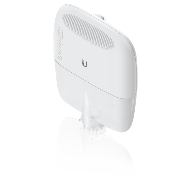
| EdgePoint Switch |
 |
|---|
| Wall-Mount Bracket |
 |
|---|
| Metal Straps (Qty. 2) |
 |
|---|
| Cable Sleeve |
 |
|---|
| Cable Ties (Qty. 20) |
 |
|---|
| S2 Hex Wrench |
 |
|---|
| Wall-Mount Screws (Qty. 4) |
 |
|---|
| Wall-Mount Anchors (Qty. 4) |
 |
|---|
| Phillips Bolts (Qty. 2) |
 |
|---|
| Gigabit PoE (54V, 1.5A) with Mounting Bracket |
 |
|---|
| Power Cord |
 |
|---|
| PoE Screws (Qty. 2) |
 |
|---|
| PoE Anchors (Qty. 2) |
Installation Requirements
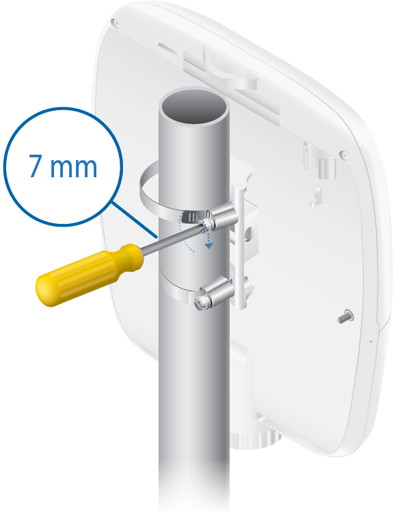
- 7 mm socket wrench
- S2 hex wrench
- Ground wire – min. 10 AWG (5 mm2) and max. length: 1 m. As a safety precaution, ground the EdgePoint to a grounded mast, pole, tower, or grounding bar.
- Shielded Category 5 (or above) cabling should be used for all wired Ethernet connections and should be grounded through the AC ground of the PoE.
We recommend that you protect your networks from harmful outdoor environments and destructive ESD events with industrial-grade, shielded Ethernet cable from Ubiquiti. For more details, visit: ui.com/toughcable
Power Options
Either the VDC or PoE input type is used at any one time. If both are connected, only the input type with the highest voltage will be used; the other can be used as a backup.
Both PoE inputs can be used at the same time. If there is a voltage difference, the higher-voltage source will be used first. The voltage from the initial source will drop as the load increases. When the voltage drops to the same level as the lower-voltage source, then the lower-voltage source will also start providing power.
Power Input Options
- 54VDC, 6A
- 54V, 1.5A on PoE In/1
- 54V, 1.5A on PoE In/2
Power Output Options
- EdgePoint (required)
- Passive 54/24V, 4-Pair PoE on 1-4
- PoE+ or Passive 24V, 2-Pair PoE on 5-16
The number of devices that can be powered depends on the power consumption of the specific devices and the power input option. Example: If you provide 54VDC, 1.5A, then you have 81W of power. If the EdgePoint uses 40W (Max. Power Consumption), then you have 41W available for passive PoE output. Check product specifications for the power consumption values to use in your calculations.
Hardware Overview
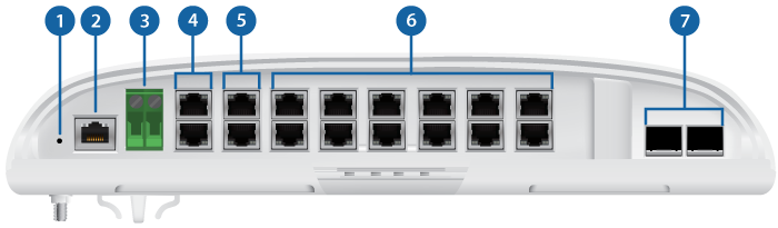
 Reset Button |
||
|---|---|---|
Click here to learn how to reset the EdgePoint to factory defaults. |
||
 Console Port |
||
RJ45 serial console port for Command Line Interface (CLI) management.
|
||
 DC Input |
||
Terminal block connector uses auto-polarity detection and accepts +42 to +56VDC, 6A input (including the Ubiquiti EdgePower™, model EP-54V-150W) to power the EdgePoint and passive PoE output. -48V is NOT supported. |
||

Ports PoE In / 1 - 2 (54/24V PoE Out) |
||
RJ45 ports support 10/100/1000 Ethernet connections and have PoE input or output functionality:
Do NOT configure port PoE In / 1 or 2 in PoE output mode if you are using it as a PoE input power source. |
||
 Ports 3 - 4 (54/24V PoE Out) |
||
RJ45 ports support 10/100/1000 Ethernet connections and passive 54/24V, 4-pair PoE output for airFiber® devices. |
||
 Ports 5 - 16 (PoE+ or 24V PoE Out) |
||
RJ45 ports support 10/100/1000 Ethernet connections and PoE+ (IEEE 802.3af/802.3at) or passive 24V, 2-pair PoE output for airMAX® or other devices. |
||
 SFP+ 1 - 2 Ports |
||
SFP+ ports are hot-swappable and support 1/10 Gbps fiber SFP/SFP+ modules.
|

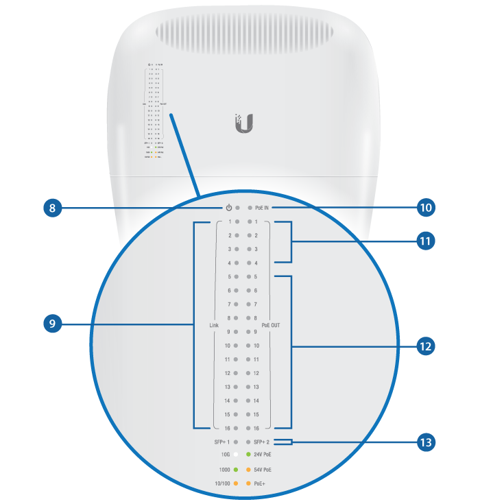

System LED |
|||
|---|---|---|---|
|
|||
Flashing White |
Bootup in progress. |
||
White |
Ready for use, not connected to Ubiquiti Internet Service Provider (UISP™). See "UISP Management". |
||
Blue |
Ready for use, connected to UISP. |
||
Steady Blue with Occasional Flashing |
Ready for use, unable to connect to UISP, check connection to UISP server. |
||
Quickly Flashing Blue |
Used to locate a device in UISP. |
||
Alternating Blue/White |
Firmware upgrade in progress. |
||

Speed/Link/Activity LED (Ports 1 - 16) |
|||
Off |
No Link |
||
Amber |
10/100 Mbps Link |
||
Green |
1000 Mbps (1 Gbps) Link |
||

PoE Input LED (Ports 1 - 2) |
|||
Off |
No PoE |
||
Green |
54V Passive |
||

PoE Output LED (Ports 1 - 4) |
|||
Off |
No PoE |
||
Amber |
54V Passive, 4-Pair |
||
Green |
24V Passive, 4-Pair |
||

PoE Output LED (Ports 5 - 16) |
|||
Off |
No PoE |
||
Amber |
PoE+ Auto (IEEE 802.3af/802.3at) |
||
Green |
24V Passive, 2-Pair |
||

Speed/Link/Activity (SFP+ 1 - 2 Ports) |
|||
Off |
No Link |
||
Green |
1000 Mbps (1 Gbps) Link |
||
White |
10 Gbps Link |
||

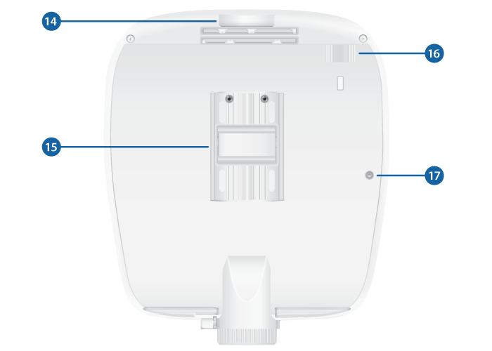
Lanyard Loop |
|||
Used for temporary support during installation. |
|||

Pole-Mount Bracket |
|||
Used for pole-mounting or in combination with the included Wall-Mount Bracket for wall-mounting. |
|||

PicoStation®M2HP Slot |
|||
Used for mounting an optional PicoStationM2HP (not included) to the back of the EdgePoint. (You can use the PicoStationM2HP for wireless management of the EdgePoint.) |
|||

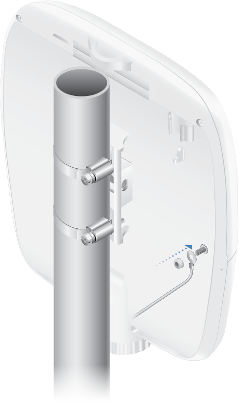
Ground Bonding Point |
|||
Used to secure a ground wire (not included). |
|||
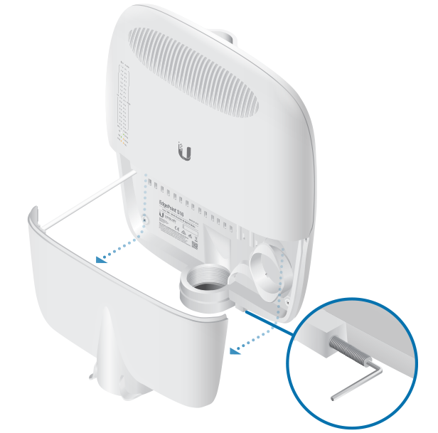
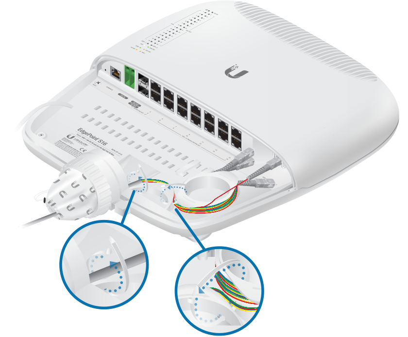
Attaching the Cable Sleeve
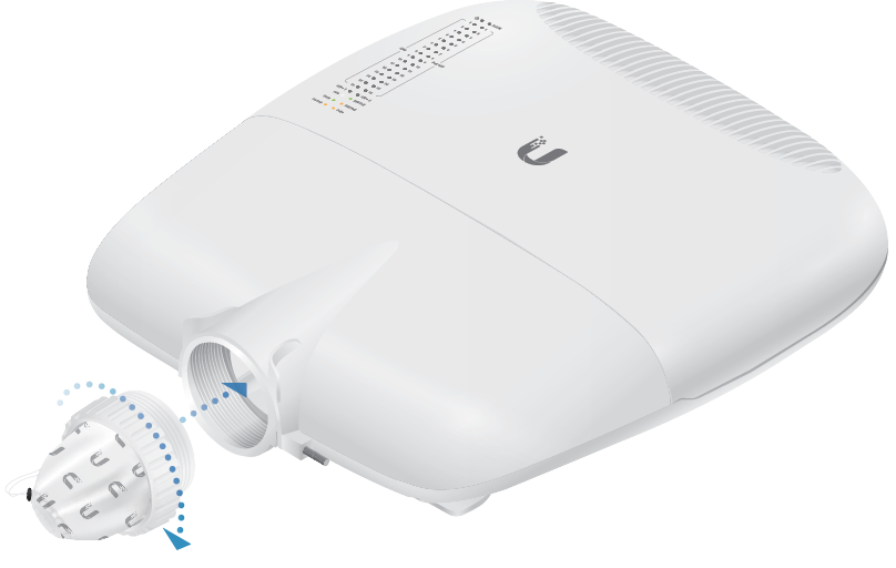
|
|
Note: You have two options for using a 2.0-inch NPT (National Pipe Thread) male conduit (not included):
|
|---|
Hardware Installation
Mount the EdgePoint on a pole or to a wall:
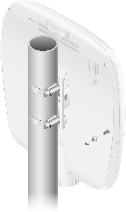
Pole-Mounting
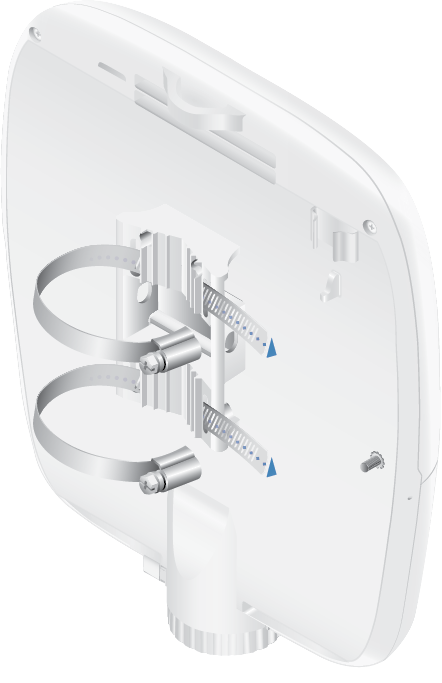
- Proceed to "Grounding the EdgePoint".
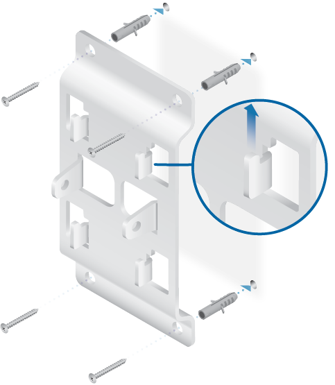
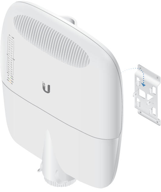
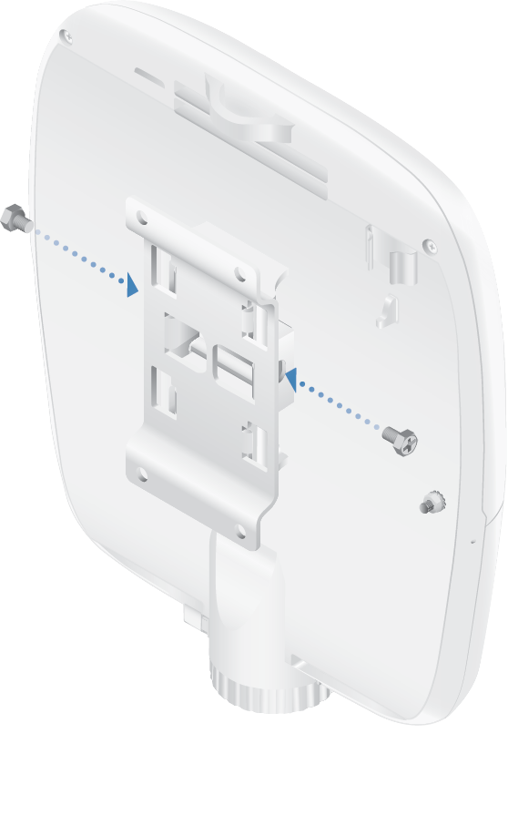
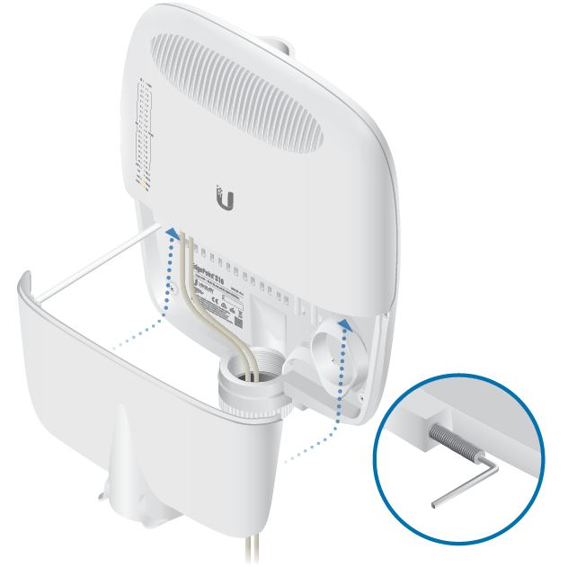
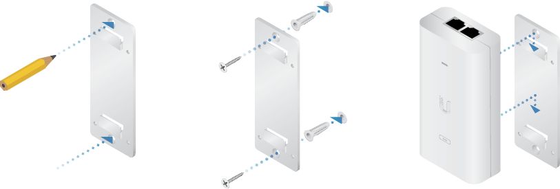
Wall-Mounting
|
|
Note: The Wall-Mount Bracket must be anchored directly to a stud or other structurally stable surface. |
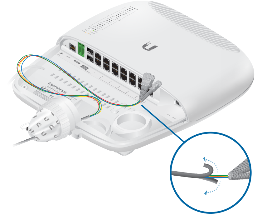
Grounding the EdgePoint
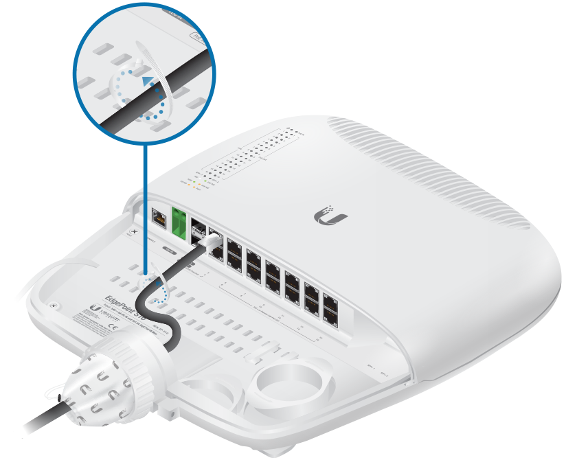
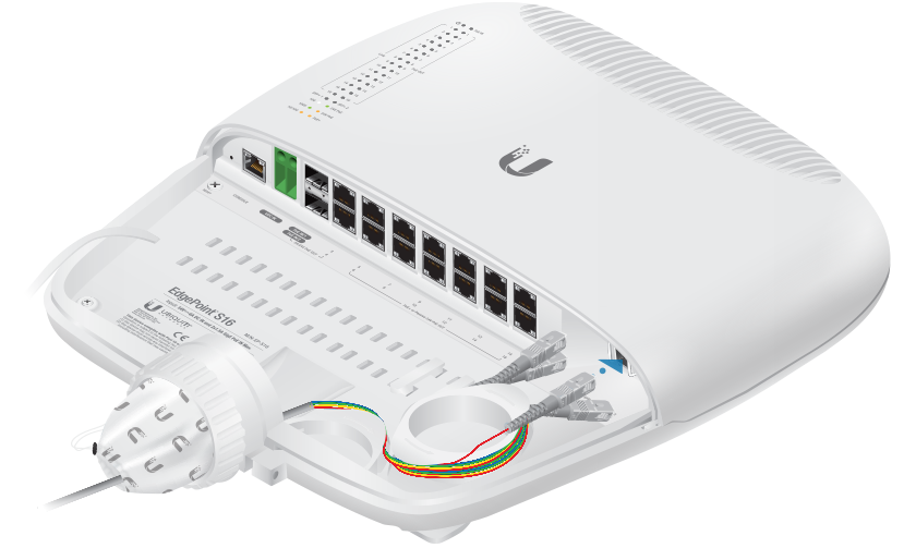
Connecting Ethernet
| Note: PoE is disabled by default. |
|---|
![]()
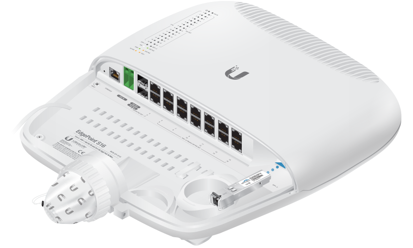
Connecting SFP+/SFP
For information about compatible fiber SFP modules, visit: ubnt.link/SFP_DAC_Compatibility
Connecting Power
Proceed to the appropriate section:
|
|
WARNING: -48V is NOT supported. |
|---|

Connecting to the VDC Input
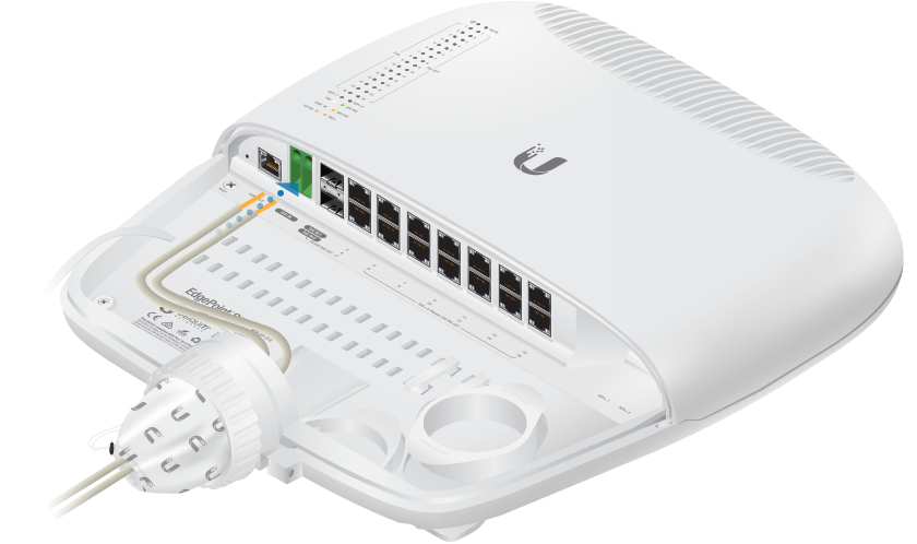
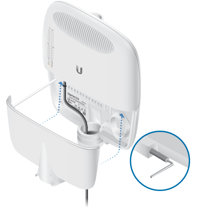
Connecting Power Using PoE
The following instructions show port PoE In / 1; however, you can use port PoE In / 2 instead.
|
|
Note: Do NOT configure port PoE In / 1 or 2 in PoE output mode if you are using it as a PoE input power source. |
|---|
Optional
Accessing the Configuration Interface
By default, the EdgePoint will try to get its IP address automatically using DHCP. If that fails, then it will use the default fallback IP address, 192.168.1.2. Proceed to the appropriate section, DHCP or "Fallback IP Address":
DHCP
Use one of the following methods:
- Set up the DHCP server to provide a specific IP address to the EdgePoint based on its MAC address (on the label).
- Let the EdgePoint obtain an IP address and then check the DHCP server to see which IP address was assigned.
To log in, follow these steps:
- Launch your web browser. Enter the appropriate in the address field. Press enter (PC) or return (Mac).
- Enter ubnt in the Username and Password fields. Click Sign in.
- The EP-S16 Configuration Interface will appear. Customize additional settings as needed.
For more information on PoE configuration, refer to "Configuring PoE Settings".
Fallback IP Address
- Ensure that your computer (or other host machine) is connected to the EdgePoint.
- Configure the Ethernet adapter on your host system with a static IP address on the 192.168.1.x subnet.
- Launch your web browser. Enter the appropriate in the address field (192.168.1.2 is the default fallback IP address). Press enter (PC) or return (Mac).

- Enter ubnt in the Username and Password fields. Click Sign In.
- The EP-S16 Configuration Interface will appear. Go to Settings
 .
. - Change the IP Address to a unique IP address. Click Apply.
|
|
Note: If you change the IP settings, then the session will be cut off, and you will need to reconnect to the EdgePoint using the new IP address. |
|---|
Customize additional settings as needed. For more information on PoE configuration, refer to "Configuring PoE Settings".
UISP Management
You can manage your device using UISP, which lets you configure, monitor, upgrade, and back up your devices using a single application. Get started at uisp.ui.com
Configuring PoE Settings
|
|
WARNING: Before activating 54V or 24V passive PoE, ensure that the connected device supports PoE and the supplied voltage. |
|---|

- Go to Dashboard
 .
. - For the Ethernet port you want to configure, click the PoE drop-down menu.
- Select the appropriate mode:
- For ports 1-4, select Off, 54V passive 4-pair, or 24V passive 4-pair.
- For ports 5-16, select Off, PoE+ auto, or 24V passive.
| WARNING: Do NOT connect 4-pair PoE devices, such as airFiber devices, to ports 5-16. They support 2-pair PoE only. |
|---|
| Note: If the PoE screen states that PoE is not supported, then there is insufficient power. You will need to increase the power input to the EdgePoint. |
|---|
For more information, refer to the EdgeSwitch™ documentation, which is available at ui.com/download/edgemax
Specifications
|
EP-S16 |
|
|
Dimensions |
326.6 x 382.7 x 88.8 mm (12.86 x 15.07 x 3.50") |
|---|---|
| With Wall-Mount | 326.6 x 382.7 x 105.5 mm (12.86 x 15.07 x 4.15") |
|
Weight |
3.4 kg (7.50 lb) |
| With Wall-Mount | 3.8 kg (8.38 lb) |
|
Max. Power Consumption |
40W (Excludes PoE Output) |
|
Power Input |
(1) DC Terminal Block or (2) RJ45 (Ports 1 and 2) (Self-Correcting Polarity Protection on DC Terminal Block Only, |
|
Power Supply |
Min. 54V / 0.8A (Excludes PoE Output Power) |
|
VDC Input |
54V / 6A |
|
Passive PoE Input |
(2) 54V / 1.5A, 4-Pair (+1, 2, 4, 5; - 3, 6, 7, 8) Passive PoE, Ports 1 and 2 (Do NOT Configure Port 1 or 2 in PoE Output Mode if You Are Using PoE Input Power Sources.) |
|
Passive PoE Output |
(4) 54V or 24V /1.4A, 4-Pair (+1, 2, 4, 5; - 3, 6, 7, 8) Passive PoE, Ports 1 to 4 (12) 802.3af/at or 24V/0.7A, 2-Pair (+ 4, 5; - 7, 8) Passive PoE, Ports 5 to 16 |
|
Power Monitoring |
(1) DC Terminal Block, Input Power (2) RJ45, Ports 1 and 2, PoE Input or Output Power (14) RJ45, Ports 3 to 16, PoE Output Power |
|
Supported Voltage Range |
+42 to +56VDC |
|
Button |
Reset |
|
LEDs |
|
| System | Power |
| PoE In | PoE |
| 1 to 16 | Speed/Link/Activity, PoE |
| SFP | Speed/Link/Activity |
|
Ports |
|
| Serial Console Port | (1) RJ45 Serial Port |
| Data Ports | (16) 10/100/1000 RJ45 Ports (2) 1/10 Gbps SFP+ Ports |
|
Pole/Wall Mount |
Yes |
|
Operating Temperature |
-40 to 65° C (-40 to 149° F) |
|
Operating Humidity |
10 - 90% Noncondensing |
|
Certifications |
CE, FCC, IC |
Safety Notices
- Read, follow, and keep these instructions.
- Heed all warnings.
- Only use attachments/accessories specified by the manufacturer.
| WARNING: Do not use this product in location that can be submerged by water. |
|---|

| WARNING: Avoid using this product during an electrical storm. There may be a remote risk of electric shock from lightning. |
|---|
Electrical Safety Information
- Compliance is required with respect to voltage, frequency, and current requirements indicated on the manufacturer’s label. Connection to a different power source than those specified may result in improper operation, damage to the equipment or pose a fire hazard if the limitations are not followed.
- There are no operator serviceable parts inside this equipment. Service should be provided only by a qualified service technician.
- This equipment is provided with a detachable power cord which has an integral safety ground wire intended for connection to a grounded safety outlet.
- Do not substitute the power cord with one that is not the provided approved type. Never use an adapter plug to connect to a 2-wire outlet as this will defeat the continuity of the grounding wire.
- The equipment requires the use of the ground wire as a part of the safety certification, modification or misuse can provide a shock hazard that can result in serious injury or death.
- Contact a qualified electrician or the manufacturer if there are questions about the installation prior to connecting the equipment.
- Protective earthing is provided by Listed AC adapter. Building installation shall provide appropriate short-circuit backup protection.
- Protective bonding must be installed in accordance with local national wiring rules and regulations.
Limited Warranty
The limited warranty requires the use of arbitration to resolve disputes on an individual basis, and, where applicable, specify arbitration instead of jury trials or class actions.
Compliance
FCC
Changes or modifications not expressly approved by the party responsible for compliance could void the user’s authority to operate the equipment.
This device complies with Part 15 of the FCC Rules. Operation is subject to the following two conditions.
- This device may not cause harmful interference, and
- This device must accept any interference received, including interference that may cause undesired operation.
This equipment has been tested and found to comply with the limits for a Class A digital device, pursuant to Part 15 of the FCC Rules. These limits are designed to provide reasonable protection against harmful interference when the equipment is operated in a commercial environment. This equipment generates, uses, and can radiate radio frequency energy and, if not installed and used in accordance with the instruction manual, may cause harmful interference to radio communications. Operations of this equipment in a residential area is likely to cause harmful interference in which case the user will be required to correct the interference at his own expense.
ISED Canada
CAN ICES-3(A)/NMB-3(A)
Australia and New Zealand
| Warning: This equipment is compliant with Class A of CISPR 32. In a residential environment this equipment may cause radio interference. |
|---|

CE Marking
CE marking on this product represents the product is in compliance with all directives that are applicable to it.
![]()