Package Contents
 |
|---|
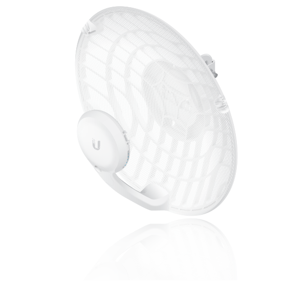
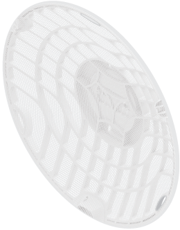
| Dish |
 |
|---|
| Main Arm |
 |
|---|
| Stabilizer Arms (Qty. 2) |
 |
|---|
| Mounting Bracket |
 |
|---|
| Screw |
 |
|---|
| U-Clamp |
 |
|---|
| Flat Washers (Qty. 2) |
 |
|---|
| Lock Washers (Qty. 2) |
 |
|---|
| Flange Nuts (Qty. 2) |
 |
|---|
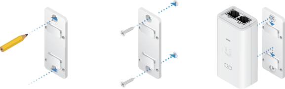
| Gigabit PoE (24V, 0.5A) with Mounting Bracket |
 |
|---|
| Power Cord |
Installation Requirements
- Clear line of sight between airFiber AP and station
- Clear view of the sky for proper GPS operation
- Vertical mounting orientation
- Mounting point:
- At least 1 m below the highest point on the structure
- For tower installations, at least 3 m below the top of the tower
- Outdoor, shielded Category 6 (or above) cabling and shielded RJ45 connectors are required for all wired Ethernet connections.
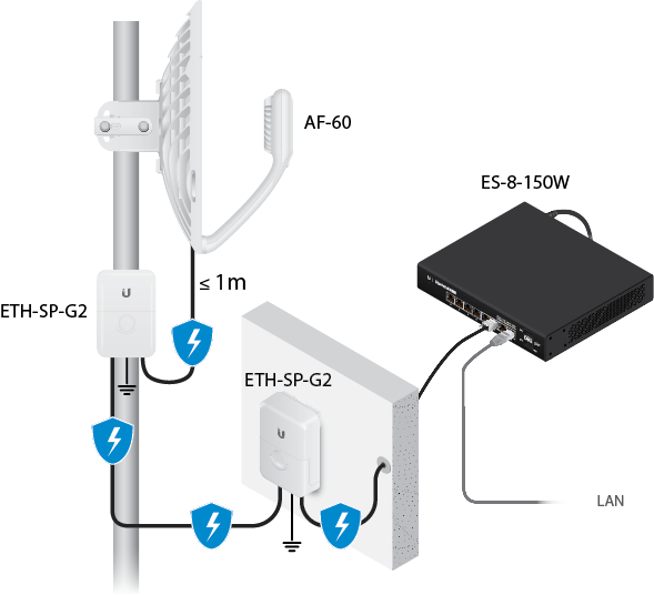
- Surge protection should be used for all outdoor installations. We recommend that you use two
Ethernet Surge Protectors, model ETH-SP-G2, one near the airFiber radio and the other at the entry
point to the building. The ETH-SP-G2 will absorb power surges and safely discharge them into the
ground.

Note: For guidelines about grounding and lightning protection, follow your local electrical regulatory codes.
Hardware Overview
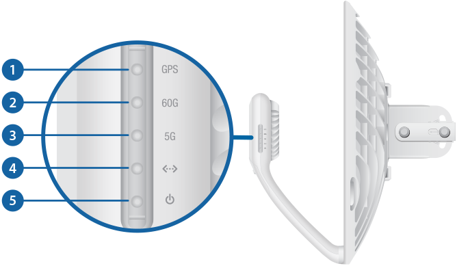

GPS LED |
|
|---|---|
|
Blue |
The LED will light blue when the GPS signal strength is sufficient. This requires a minimum of three GPS satellite connections. |

60G LED |
|
|
Blue |
The LED will light blue when the 60 GHz link is ready. |

5G LED |
|
|
Blue |
The LED will light blue when the 5 GHz link is ready. |

LAN LED |
|
|
Blue |
The LED will light steady blue when an active Ethernet connection is made to the Ethernet port and flash when there is activity. |

Power LED |
|
|
Flashing White |
Bootup in progress. |
|
White |
Ready for use, not connected to Ubiquiti® Internet Service Provider (UISP™). See “UISP Management”. |
|
Blue |
Ready for use, connected to UISP. |
|
Steady Blue with Occasional Flashing |
Ready for use, unable to connect to UISP, check connection to UISP server. |
|
Quickly Flashing Blue |
Used to locate a device in UISP. |
|
Alternating |
Firmware upgrade in progress. |

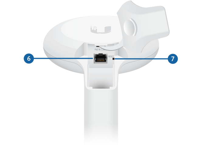
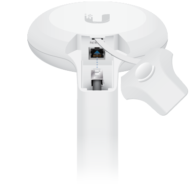
PoE IN |
|
|
Gigabit Ethernet PoE port for handling all user traffic and powering the device. Default IP address: 192.168.1.20. |
|

Reset Button |
|
|
To reset to factory defaults, press and hold the Reset button for more than 10 seconds while the device is powered on. Alternatively, the device may be reset remotely via a Reset button located on the bottom of the Gigabit PoE Adapter. |
|
Installation Overview
We recommend configuring both airFiber radios (Access Point and Station) before site installation. Follow the instructions in “Configuration” for each radio.
Configuration
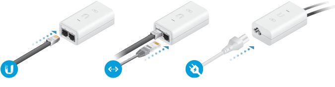
Connecting Power over Ethernet
Configuring the Settings
The device is set to DHCP by default, so it will try to automatically obtain an IP address. If that fails, it will use the default fallback IP address, 192.168.1.20. Proceed to the appropriate section, “DHCP” or “Fallback IP Address”:
DHCP
Use one of the following methods:
- Set up the DHCP server to provide a specific IP address to the device based on its MAC address (on the label).
- Let the device obtain an IP address and then check the DHCP server to see which IP address was
assigned.
- Launch your web browser. Type the appropriate address in the address field. Press enter (PC) or return (Mac).
- Select your Country and Language. You must agree to the Terms of Use to use the product. Click Continue.
- Enter a Username and Password, confirm the Password, and click Save.
- Click the
 icon.
icon.
- Configure the following settings:
- For one airFiber radio, enable Access Point mode. For the other airFiber radio (the Station), keep Access Point disabled.
- Enter a name in the SSID field. This must be the same on both the AP and the Station.
- In the WPA2 Preshared Key field, enter a combination of alphanumeric
characters (0-9, A-Z, or a-z).
Note: The key is an alphanumeric password between 8 and 63 characters long.
- Click Save Changes.
- Configure each airFiber radio with a unique IP address:
- Click the
 icon.
icon. - Review the Network settings to ensure that each airFiber radio has a
unique IP address. Each can get its IP address via DHCP, or use a static IP address.
- DHCP By default DHCP client is enabled; if
there is a DHCP server on your network, the airFiber radio will receive its
address via DHCP.
Note: If DHCP client fails, the device will use the fallback IP address: 192.168.1.20
- Static IP You can disable the DHCP client and use a static IP address.
- DHCP By default DHCP client is enabled; if
there is a DHCP server on your network, the airFiber radio will receive its
address via DHCP.
- Click Save Changes.
- Click the
Fallback IP Address
- Ensure that your computer (or other host machine) is connected to the same LAN as the airFiber radio.
- Configure the Ethernet adapter on your host system with a static IP address on the 192.168.1.x subnet.
- Launch your web browser. Type https://192.168.1.20 in the address field, and press
enter (PC) or return (Mac).

- Select your Country and Language. You must agree to the Terms of Use to use the product. Click Continue.
- Enter a Username and Password, confirm the Password, and click Save.
- Click the
icon.
- Configure the following settings:
- For one airFiber radio, enable Access Point mode. For the other airFiber radio (the Station), keep Access Point disabled.
- Enter a name in the SSID field. This must be the same on both the AP and the Station.
- In the WPA2 Preshared Key field, enter a combination of alphanumeric characters
(0-9, A-Z, or a-z).
Note: The key is an alphanumeric password between 8 and 63 characters long.
- Click Save Changes.
- Configure each airFiber radio with a unique IP address:
- Click the icon.
- Review the Network settings to ensure that each airFiber radio has a unique IP
address. Each can get its IP address via DHCP, or use a static IP address.
- DHCP By default DHCP client is enabled; if there is a DHCP server on your network, the airFiber radio will receive its address via DHCP.
- Fallback IP If you use the fallback IP address on one radio, you must change the IP Address setting on the other radio. The fallback IP address is: 192.168.1.20
- Click Save Changes.
- Click the
UISP Management
You can manage your device using UISP, which lets you configure, monitor, upgrade, and back up your devices using a single application. Get started at uisp.ui.com
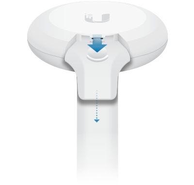
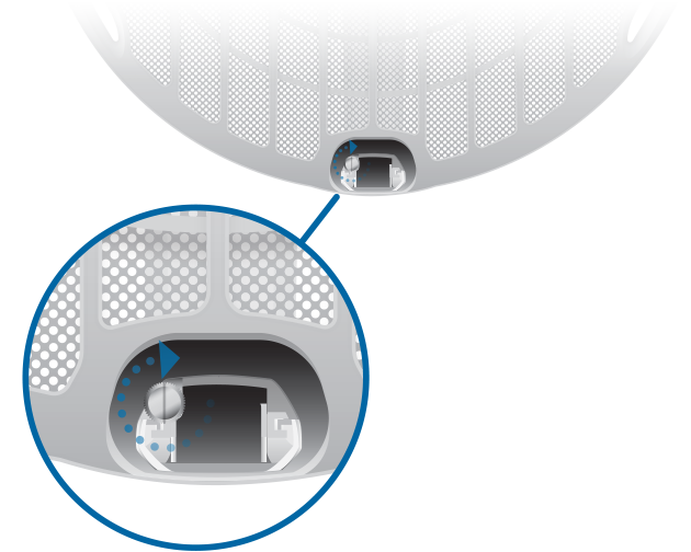
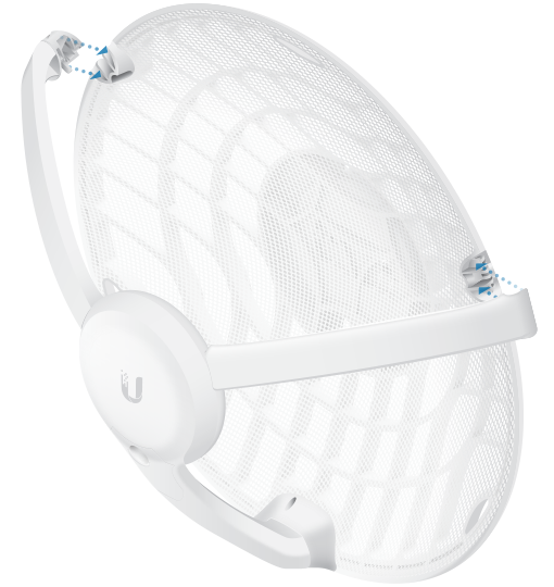
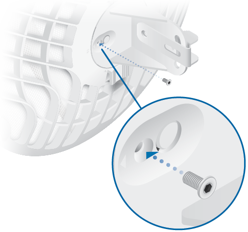
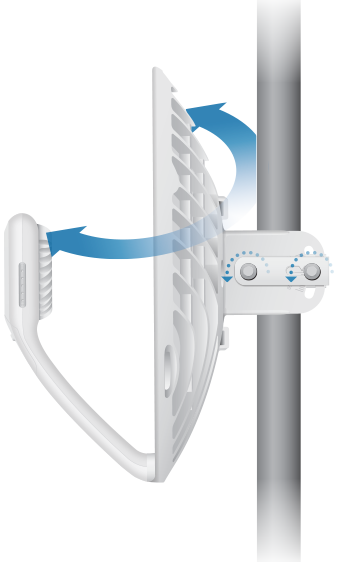
Installation
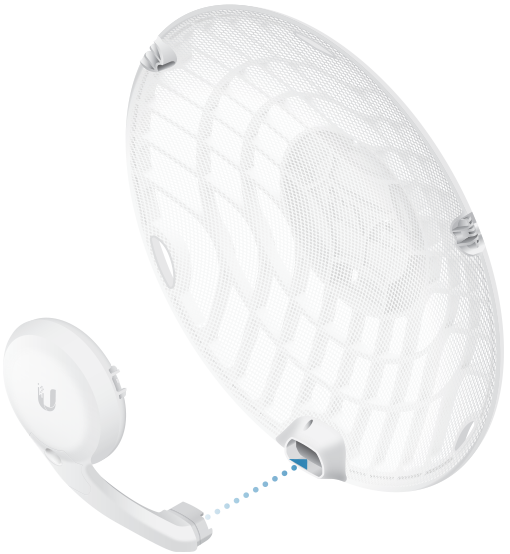
Optional
Attach the stabilizer arms for added support.
(This is
recommended for long-range installations.)
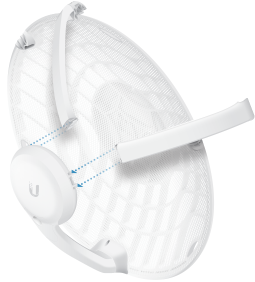
|
|
Note: The AF60 can mount on either side of the pole. This section shows the AF60 mounted on the left; the procedure for mounting on the right is similar. |
|---|
|
Left |
OR |
Right |
|
|
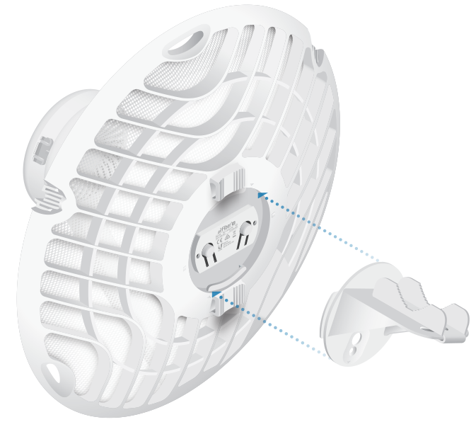
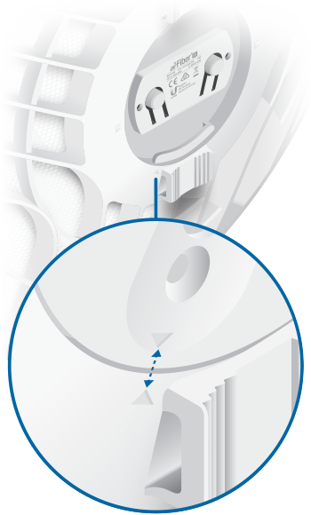
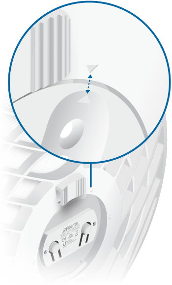
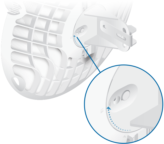
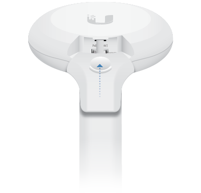
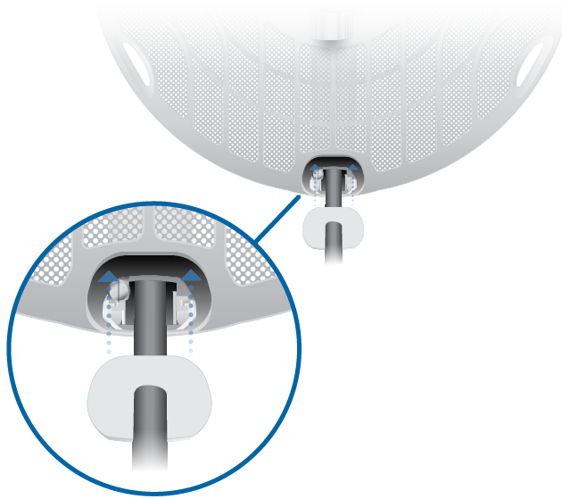
Note: Rotate the Mounting Bracket clockwise until it locks into position. |
|---|
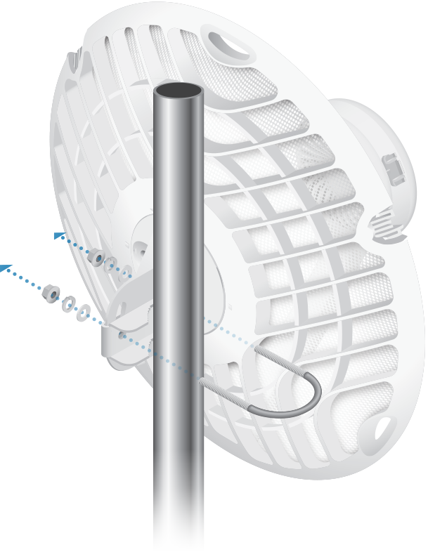
(Pole not shown)
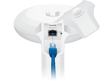
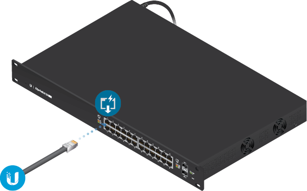
Connecting Power
|
|
WARNING: The switch port must comply with the power specifications listed in “Specifications”. |
|---|

OR
Optional
Alignment
Tips
- To accurately align the airFiber radios for best performance, you MUST align only one end of the link at a time.
- You may need to use additional hardware to compensate for issues such as the improper orientation of a mounting pole or significant elevation differences between airFiber radios.
Establishing a Link
Adjust the aim of the AP and the Station to establish a link.
|
|
Note: The AP must be aimed first at the Station because the Station does not transmit any RF signal until it detects transmissions from the AP. |
|---|
- AP Visually aim the AP at the Station by
loosening the Flange Nuts on the Mounting Bracket to allow adjustments to the azimuth and the
elevation.
Adjust the azimuth:
Adjust the elevation:
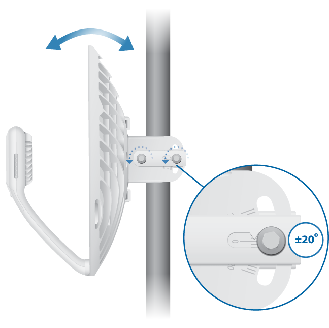
Note: Do NOT make simultaneous adjustments on the AP and Station.
- Station Visually aim the Station at the AP. To adjust the Station’s position, adjust the azimuth and elevation as described in step 1.
- Open the Configuration Interface, select Tools, and then select Align Antenna.
- Repeat steps 1-2 until you have achieved an optimal link and both the 60G and 5G LEDs are solidly
lit blue. This ensures the best possible data rate between the airFiber radios.
Note: Maximum signal strength can best be achieved by iteratively sweeping through both azimuth and elevation.
- Lock the alignment on both airFiber radios by tightening all the nuts.
- Observe the signal level of each airFiber radio to ensure that the values remain constant while tightening the nuts. If any value changes during the locking process, loosen the nuts, finalize the alignment of each airFiber radio again, and retighten the nuts.
Installer Compliance Responsibility
Devices must be professionally installed and it is the professional installer’s responsibility to make sure the device is operated within local country regulatory requirements.
Antenna
The 5GHz Output Power field is provided to the professional installer to assist in meeting regulatory requirements.
Specifications
|
AF60 |
|
|
Dimensions |
413 x 413 x 320 mm |
|---|---|
|
Weight |
|
| Without Mount | 1.4 kg (3.09 lb) |
| With Mount | 1.8 kg (3.97 lb) |
|
Enclosure |
Aluminum, UV-stabilized Polycarbonate |
|
Antenna Gain |
|
| 5 GHz | 11 dBi |
| 60 GHz | 38 dBi |
|
Networking Interface |
(1) 10/100/1000 Mbps Ethernet Port |
|
Max. Power Consumption |
11W |
|
Power Method |
Passive PoE, Pins 4, 5+ and 7, 8- |
|
Power Supply |
24VDC, 0.5A Gigabit PoE Adapter (Included) |
|
Voltage Range |
+22 to +26VDC |
|
LEDs |
Power/Ethernet/5G/60G/GPS |
|
Mounting |
Pole Mount (Included) |
|
Wind Loading |
420 N @ 200 km/h |
|
Wind Survivability |
200 km/h |
|
ESD/EMP Protection |
± 24kV Contact/Air |
|
Operating Temperature |
-40 to 60° C (-40 to 140° F) |
|
Operating Humidity |
5 to 95% Noncondensing |
|
Certifications |
FCC, IC, CE |
|
System |
|
|
Maximum Throughput |
1.8 Gbps |
|---|---|
|
Maximum Range |
2+ km |
|
Encryption |
WPA2-PSK (AES)/WPA2 Enterprise |
|
OS |
airOS GP |
|
Radio |
|
|
Max. Conducted TX Power |
|
|---|---|
| 5/60 GHz Combined | 25 dBm |
|
Channel Bandwidth |
|
| 60 GHz | 2160 MHz |
| 5 GHz | 20/40/80 MHz |
|
Operating Frequency (MHz) |
||
|
US/CA |
U-NII-1 |
5150 - 5250 |
|---|---|---|
|
U-NII-2A |
5250 - 5350 |
|
|
U-NII-2C |
5470 - 5725 |
|
|
U-NII-3 |
5725 - 5850 |
|
|
57,000 - 67,000 |
||
|
Worldwide |
5180 - 5875 |
|
|
Management Radio (MHz) |
|
|
Worldwide |
2412 - 2472 |
|---|---|
|
US/CA |
2412 - 2462 |