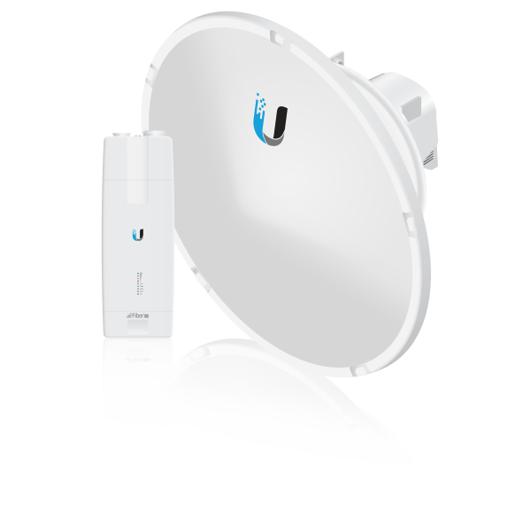
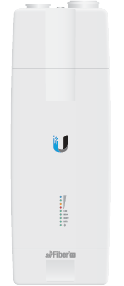
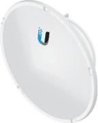
Package Contents
 |
|---|
| airFiber AF-11 Radio* |
 |
|---|
| Zip Ties (Qty. 2) |
 |
|---|
| airFiber Gigabit PoE (50V, 1.2A) |
 |
|---|
| Power Cord |
 |
|---|
| AF-11G35 Antenna |
 |
|---|
| Shroud |
 |
|---|
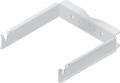
| I-Bracket |
 |
|---|
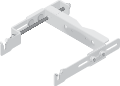
| Upper Mount Bracket with Elevation Rod |
 |
|---|
| Lower Mount Bracket |
 |
|---|
| Pole Clamps (Qty. 2) |
 |
|---|
| Azimuth Support Brackets (Qty. 2) |
 |
|---|
| RF Cables (Qty. 2) |
 |
|---|
| Large Carriage Bolts (Qty. 4) |
 |
|---|
| Small Carriage Bolts (Qty. 2) |
 |
|---|
| Serrated Flange Bolts (Qty. 4) |
 |
|---|
| Bolts with Washers (Qty. 4) |
 |
|---|
| Serrated Flange Nuts (Qty. 6) |
* Comes with (1) Low-Band or (1) High-Band Duplexer pre-installed for SISO mode. For MIMO mode, a second Duplexer is available, model AF-11-DUP-L or AF-11-DUP-H.
Installation Requirements
- Clear line of sight between airFiber radios
- Vertical mounting orientation
- Mounting point:
- At least 1 m below the highest point on the structure
- For tower installations, at least 3 m below the top of the tower
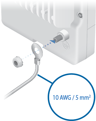
- Ground wires – min. 10 AWG (5 mm2) and max. length: 1 m. As a safety
precaution, ground the airFiber radio to grounded masts, poles, towers, or grounding bars.

WARNING: Failure to properly ground your airFiber radio will void your warranty.
- (Optional) MIMO mode: A second Duplexer of the same band type: Low-Band
Duplexer (model AF-11-DUP-L) or High-Band Duplexer (model AF-11-DUP-H):

Note: The AF-11 radio has one Duplexer pre-installed for SISO mode. For MIMO mode, a second Duplexer must be purchased separately. The Duplexer(s) must match the terms of your license (frequency bands and polarities allowed).
- (Optional) If not using PoE: DC power source and 12/30 AWG power cable
- Outdoor, shielded Category 6 (or above) cabling and shielded RJ-45 connectors are required for all wired Ethernet connections.
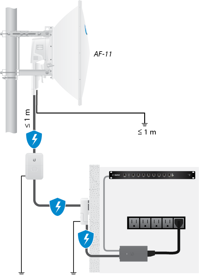
- (Recommended) Surge protection should be used for all outdoor installations. We recommend that you
use two Ethernet Surge Protectors, model ETH-SP-G2, one within one meter of the device and the other
at the entry point to the building. The ETH-SP-G2 will absorb power surges and safely discharge them
into the ground.
Note: For guidelines about grounding and lightning protection, follow your local electrical regulatory codes.
Hardware Overview

 |
 |
|
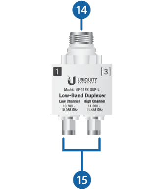
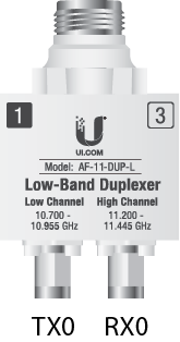
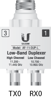
Low-Band Duplexer |
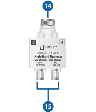
High-Band Duplexer |

Chain 0 / Chain 1 |
|||||||||||||||||||||||||||||||||||||||||||||
|---|---|---|---|---|---|---|---|---|---|---|---|---|---|---|---|---|---|---|---|---|---|---|---|---|---|---|---|---|---|---|---|---|---|---|---|---|---|---|---|---|---|---|---|---|---|
|
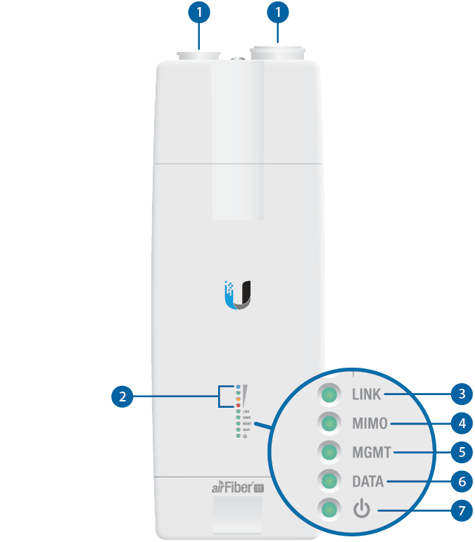
When the Chain 0 or Chain 1 duplexer is installed, its N-type connector is located here, allowing connection to an RF cable (Chain 1 is covered by the removable Duplexer Cap). |
|||||||||||||||||||||||||||||||||||||||||||||

Signal LEDs |
|||||||||||||||||||||||||||||||||||||||||||||
Bootup to airOS When powering on, the Power, MIMO, LINK, and Signal 1-4 LEDs light on. Once the CPU code takes over, the MIMO, LINK, and Signal 1-3 LEDs turn off. Signal 4 LED remains lit to indicate the boot sequence is underway. Initializing airFiber Software When the airFiber application begins to boot under airOS, the Signal 4 LED goes from solidly on to a 2.5 Hz flash. This continues until the device is fully booted. Signal Level Once fully booted, the Signal 1-4 LEDs act as a bar graph showing how close the device is to ideal aiming. This is auto-scaled based on the link range, the antenna gains, and the configured TX power of the remote device. Each Signal LED has three possible states: On, Flashing, and Off. All Signal LEDs would be solidly on in an ideal link. For example, if the link has a 1 dB loss, the Signal 4 LED will flash; a 2 dB loss and the Signal 4 LED will turn off. The full bar graph LED states are shown below.
|
|||||||||||||||||||||||||||||||||||||||||||||

Link LED |
|||||||||||||||||||||||||||||||||||||||||||||
|
Off |
RF Off |
||||||||||||||||||||||||||||||||||||||||||||
 |
Syncing |
||||||||||||||||||||||||||||||||||||||||||||
 |
Beaconing |
||||||||||||||||||||||||||||||||||||||||||||
 |
Registering |
||||||||||||||||||||||||||||||||||||||||||||
|
On |
Operational |
||||||||||||||||||||||||||||||||||||||||||||

MIMO LED |
|||||||||||||||||||||||||||||||||||||||||||||
|
Off |
Radio Configured in SISO Mode |
||||||||||||||||||||||||||||||||||||||||||||
|
On |
Radio Configured in MIMO Mode |
||||||||||||||||||||||||||||||||||||||||||||

MGMT LED |
|||||||||||||||||||||||||||||||||||||||||||||
|
Off |
No Ethernet Link |
||||||||||||||||||||||||||||||||||||||||||||
|
On |
Ethernet Link Established |
||||||||||||||||||||||||||||||||||||||||||||
|
Random Flash |
Ethernet Activity |
||||||||||||||||||||||||||||||||||||||||||||

Data LED |
|||||||||||||||||||||||||||||||||||||||||||||
|
Off |
No Ethernet Link |
||||||||||||||||||||||||||||||||||||||||||||
|
On |
Ethernet Link Established |
||||||||||||||||||||||||||||||||||||||||||||
|
Random Flash |
Ethernet Activity |
||||||||||||||||||||||||||||||||||||||||||||

Power LED |
|||||||||||||||||||||||||||||||||||||||||||||
|
Off |
No Power |
||||||||||||||||||||||||||||||||||||||||||||
|
On |
Powered On |
||||||||||||||||||||||||||||||||||||||||||||

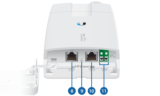
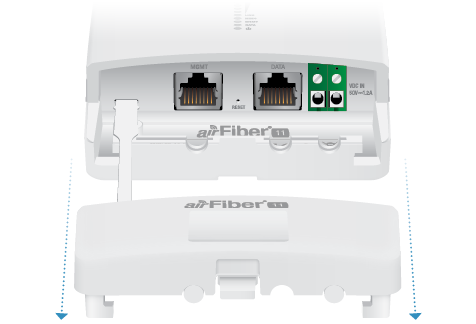
Management Port |
|||||||||||||||||||||||||||||||||||||||||||||
|
10/100 Mbps, secured Ethernet port for configuration. In-Band Management is enabled by default in the airFiber Configuration Interface. When In-Band Management is disabled, the MGMT port is the only port that can monitor, configure, and/or update firmware. |
|||||||||||||||||||||||||||||||||||||||||||||

Reset Button |
|||||||||||||||||||||||||||||||||||||||||||||
|
To reset to factory defaults, press and hold the Reset button for more than 10 seconds while the device is already powered on. |
|||||||||||||||||||||||||||||||||||||||||||||

Data Port |
|||||||||||||||||||||||||||||||||||||||||||||
|
Gigabit PoE port for handling all user traffic and powering the device. |
|||||||||||||||||||||||||||||||||||||||||||||

VDC IN |
|||||||||||||||||||||||||||||||||||||||||||||
|
The terminal block can be used to power the AF‑11 radio with +50VDC, 1.2A instead of PoE. |
|||||||||||||||||||||||||||||||||||||||||||||

TX 0, RX 0 |
|||||||||||||||||||||||||||||||||||||||||||||
|
The TX and RX SMA ports for the Chain 0 Low-Band Duplexer or High-Band Duplexer (SISO and MIMO modes). |
|||||||||||||||||||||||||||||||||||||||||||||

RX 1, TX 1 |
|||||||||||||||||||||||||||||||||||||||||||||
|
The RX and TX SMA ports for the Chain 1 Low-Band Duplexer or High-Band Duplexer (MIMO mode). In SISO mode, these unused ports are protected by the Duplexer Cap. |
|||||||||||||||||||||||||||||||||||||||||||||

N Connector |
|||||||||||||||||||||||||||||||||||||||||||||
|
Female N-type connector to which the antenna cable is attached. |
|||||||||||||||||||||||||||||||||||||||||||||

SMA Port |
|||||||||||||||||||||||||||||||||||||||||||||
|
High-band and low-band channel SMA ports. |
|||||||||||||||||||||||||||||||||||||||||||||


|
|
Note: One Low-Band Duplexer or High-Band Duplexer is pre-installed in the radio for SISO mode. MIMO mode requires two Duplexers of the same band type. |
|---|
Installation Overview
We recommend that you configure your paired radios before site installation.
- Install the Duplexer(s) in the radio.
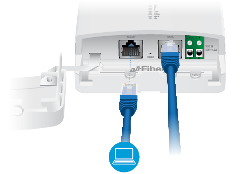
- Connect the airFiber Gigabit PoE adapter to the DATA port, and connect your computer to the MGMT port.
- Configure the radio.
- Install a ground wire and mount the radio on the airFiber AF-11G35 antenna (or a compatible antenna).
- At the installation site, install the antenna with the mounted radio (see the antenna’s Quick Start Guide for installation instructions).
- Connect the DATA port to your LAN, and connect power (PoE or DC power) to the radio.
- Establish and optimize the RF link.
Installing the Duplexers
SISO Mode Installation
Each AF-11 radio already contains one Low-Band Duplexer or one High-Band Duplexer for SISO mode. However, before you install the radios, you must ensure that Duplexers in the paired radios are positioned in the reverse order from each other.
|
|
Note: For example, if the numbers on the first radio’s Duplexer are (left to right) 1/3, then the numbers on the second radio’s Duplexer should be 3/1. |
|---|
 |
 |
|
Radio 1 |
Radio 2 |
Ensure that the Duplexers in your paired radios are installed in this manner. For instructions on how to access the Duplexers and remove or install them, see “MIMO Mode Installation”.
MIMO Mode Installation
|
|
Note: MIMO operation requires two licenses, one per polarization, and two Duplexers of the same band type. |
|---|
-
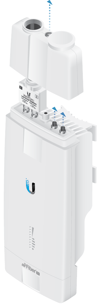
-
-
-
-
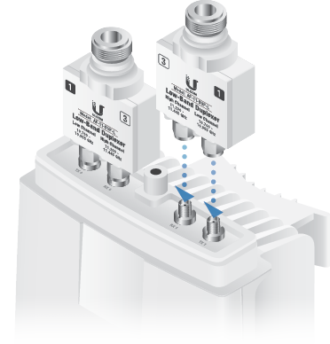
- Repeat steps 1-5 for the other radio in the link, ensuring that the numbers on the second radio’s Duplexers are in the reverse order of the numbers on the first radio’s Duplexers.
|
|
Note: Position the low channel and high channel ports to yield the required transmit and receive frequencies. Also, ensure that the numbers on the right-side Duplexer are in the reverse order of the numbers on the left-side Duplexer. |
|---|
|
|
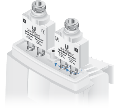
WARNING: Tighten the collars alternately, a half turn at a time, until both are fully tightened. Failure to do so may result in damage to the Duplexer. |
|---|
|
|
Note: For example, if the numbers on the first radio’s Duplexers are (left to right) 2/4 and 4/2, the numbers on the second radio’s Duplexers should be 4/2 and 2/4. |
|---|
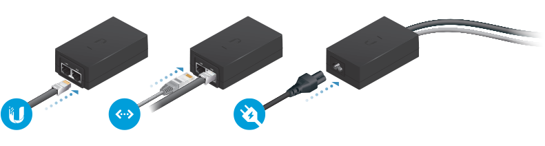
Connecting Power over Ethernet
|
|
WARNING: Use only the included adapter, model POE-50-60W. Failure to do so can damage the unit and void the product warranty. |
|---|
airFiber Configuration
Access the airFiber Configuration Interface and configure the following settings:
- Wireless Mode Configure one radio as the Master and the other as the Slave.
- Frequency Setting The TX Frequency and RX
Frequency settings must be the reverse of each other on both the Master and the Slave.
-
- Configure the Ethernet adapter on your computer with a static IP address on the 192.168.1.x subnet.
- Launch your web browser. Type https://192.168.1.20 in the address field and
press enter (PC) or return (Mac).

- Enter ubnt in the Username and Password fields. Select your Country and Language. You must agree to the Terms of Use to use the product. Click Login.
- Click Settings, and then click the Wireless tab.
- Configure the Basic Wireless Settings:
- For one radio, select Master as the Wireless Mode. For the other radio, keep the default, Slave.
- Enter a name in the Link Name field. This should be the same on both the Master and the Slave.
- If needed, change the Channel Bandwidth, Output Power and/or Maximum Modulation Rate settings.
- Configure the TX Frequency and RX Frequency.
Note: One airFiber radio’s TX Frequency is the other radio’s RX Frequency, and vice versa.
- Configure the Wireless Security:
- Select the Key Type, HEX or ASCII.
- For the Key field:
- HEX Enter 16 bytes (eight, 16-bit hexadecimal
digits: 0-9, A-F, or a-f). You can omit zeroes and use colons, similar to
the IPv6 format.
Note: The airFiber Configuration Interface supports IPv6 formats excluding dotted quad and “::” (double-colon) notation.
- HEX Enter 16 bytes (eight, 16-bit hexadecimal
digits: 0-9, A-F, or a-f). You can omit zeroes and use colons, similar to
the IPv6 format.
- ASCII Enter a combination of alphanumeric characters (0-9, A-Z, or a-z).
- Click Save Changes.
- In-Band Management is enabled by default, so each airFiber radio must have a
unique IP Address. (If the airFiber radios use the same IP
Address, you may lose access to the airFiber radios via the DATA
ports.) Click the Network tab.
- For the Management IP Address option:
- DHCP Keep the default, DHCP, to use DHCP reservation on your router to assign a unique IP Address.
- Static Change the IP Address, Netmask, and other settings to make them compatible with your network.
- Click Save Changes.
- For the Management IP Address option:
- Disconnect the Ethernet cables from the MGMT and DATA ports on the radio. Configuration of the radio is complete.
-
Repeat the instructions in the airFiber Configuration section on the other radio.
For details on the airFiber Configuration Interface, refer to the airFiber AF-11FX User Guide, available at: ui.com/download/airfiber
UISP Management
You can manage your device using UISP, which lets you configure, monitor, upgrade, and back up your devices using a single application. Get started at uisp.ui.com
Hardware Installation
Install a Ground Wire
-
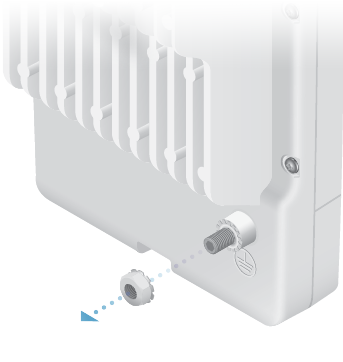
-
- At the installation site, secure the other end of the ground wire to a grounded mast, pole, tower,
or grounding bar.
WARNING: Failure to properly ground your airFiber radio will void your warranty.
Note: The ground wire should be as short as possible and no longer than one meter in length.
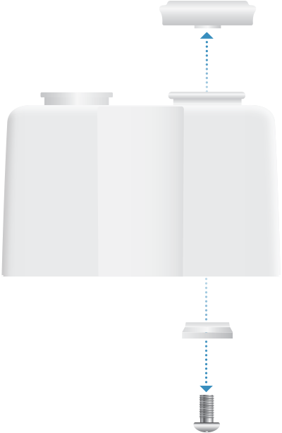
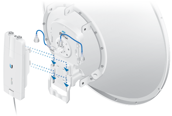
Mount to the airFiber AF-11G35 Antenna
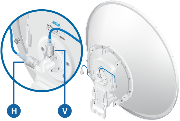
- Attach an RF Cable to an RF connector labeled H or V. Then slide the silicone boot over the RF connector to protect it.
-
-
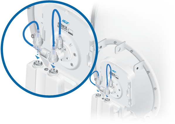
|
|
Note: For SISO mode, use the RF connector (H or V) as determined by your licensing. Keep the other RF connector covered with the included Metal Cap. |
|---|
If using MIMO mode, remove the cap over the second RF connector (V or H) and attach an RF Cable. Then slide the silicone boot over the RF connector to protect it.
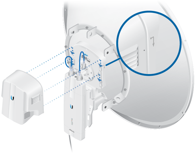
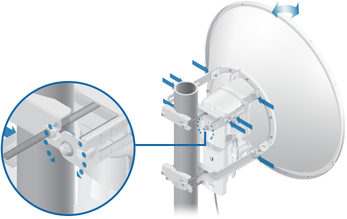
|
|
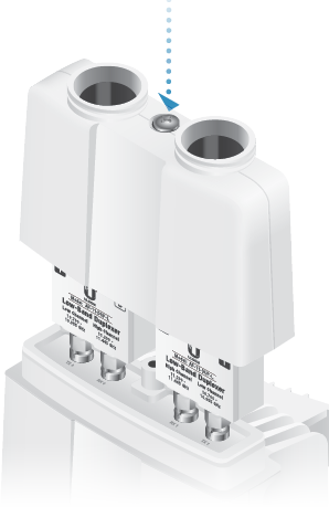
Note: Align the dot on the side of the shroud with the arrowhead on the dish antenna. |
|---|
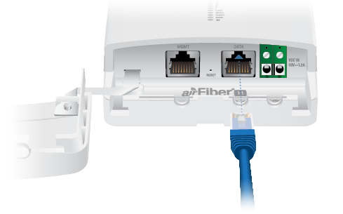
Connecting Data
-
-
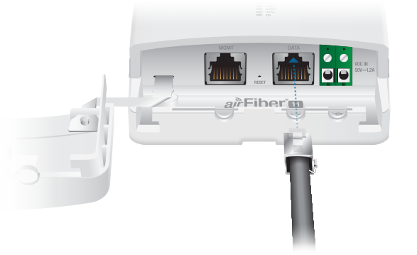
- If you are using DC power, connect the other end of the Ethernet cable to your LAN.
Connecting Power
Follow the instructions for the source of power that you are using:
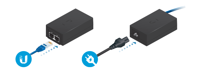
Power Over Ethernet
|
|
WARNING: Use only the included adapter, model POE-50-60W. Failure to do so can damage the unit and void the product warranty. |
|---|
DC Power
- Connect a DC power cable to the Terminal Block. (The +VDC and GND can be connected to
either terminal.)
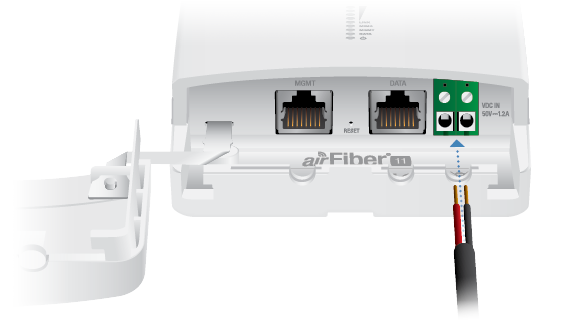
- Connect the other end of the DC power cable to a DC power supply that supplies +50VDC.
- Connect the DC power supply to its source.
|
|
WARNING: Applying a negative voltage such as -48VDC will damage the radio. |
|---|
Alignment
Tips
- To accurately align the airFiber radios for best performance, you MUST align only one end of the link at a time.
- You may need to use additional hardware to compensate for issues such as the improper orientation of a mounting pole or significant elevation differences between airFiber radios.
Establishing a Link
Adjust the positions of the Master and the Slave to establish a link. The following section features the airFiber X antenna, AF-11G35:
|
|
Note: The Master must be aimed first at the Slave because the Slave does not transmit any RF signal until it detects transmissions from the Master. |
|---|
- Master Visually aim the Master at the Slave.
To adjust the Master’s position, adjust the azimuth and the elevation.
Adjust the azimuth:
- Loosen the four flange nuts on the two pole clamps.
- Rotate the antenna to point towards the other end of the link.
- Tighten the four flange nuts on the two pole clamps.
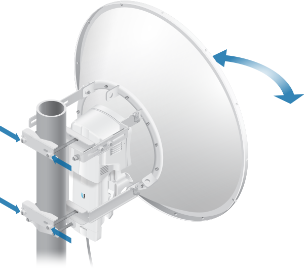
Adjust the elevation angle:
- Loosen the eight hex head bolts so that the washers can spin freely by hand.
- Tighten or loosen the Elevation Adjustment Bolt to set the desired tilt.
- Tighten the eight hex head bolts.
- Slave Visually aim the Slave at the Master. To adjust the Slave’s position, adjust the azimuth and elevation as described in step 1.
- Check to see if a link is established. Ensure that the LINK LED is solidly lit green
and the Signal LEDs of the Slave are displaying signal levels.

- Slave Aim the Slave at the Master to achieve
the strongest signal level on the Master.
Note: Refer to the Signal LEDs section for details on the signal values.
Note: Maximum signal strength can best be achieved by iteratively sweeping through both azimuth and elevation.
- Master Aim the Master at the Slave to achieve the strongest signal level on the Slave.
- Repeat steps 4 and 5 until you achieve an optimal link, with all four Signal LEDs solidly lit. This ensures the best possible data rate between the airFiber radios.
- Lock the alignment on both airFiber antennas by tightening all the nuts and bolts.
- Observe the Signal LEDs of each airFiber radio to ensure that the values remain constant while tightening the nuts and bolts. If any LED value changes during the locking process, loosen the nuts and bolts, finalize the alignment of each airFiber antenna again, and retighten the nuts and bolts.
|
|
Note: Do NOT make simultaneous adjustments on the Master and Slave. |
|---|
For detailed information on setting up an airFiber link, see the airFiber AF-11FX User Guide available at: ui.com/download/airfiber
Installer Compliance Responsibility
Devices must be professionally installed and it is the professional installer’s responsibility to make sure the device is operated within local country regulatory requirements.
The Output Power, Antenna Gain, Cable Loss*, TX Frequency and RX Frequency fields are provided to the professional installer to assist in meeting regulatory requirements.
* Cable Loss includes loss due to the Duplexer(s).
Specifications
|
airFiber AF-11 |
|
|
Dimensions |
327 x 112 x 86 mm (12.87 x 4.41 x 3.39") |
|---|---|
|
Weight |
2.26 kg (5.0 lb) |
|
RF Connectors |
(4) SMA Weatherproof, Two per Chain: |
|
Power Supply |
50V, 1.2A PoE Gigabit Adapter (Included) |
|
Power Method |
Passive Power over Ethernet, DC Power Block |
|
Supported Voltage Range |
38-56VDC |
|
Certifications |
FCC Part 101, ETSI EN 302 217 |
|
Mounting |
AF-11G35 Mount Compatible |
|
Operating Temperature |
-40 to 55° C (-40 to 131° F) |
|
Networking Interface |
|
| Data | (1) 10/100/1000 Ethernet Port |
| Management | (1) 10/100 Ethernet Port |
|
System |
|
|
Processor |
INVICTUS™ 2 IC |
|---|---|
|
Maximum Throughput |
1.2+ Gbps |
|
Encryption |
128-bit AES |
|
OS |
airOS F |
|
Wireless Modes |
SISO/MIMO |
|
Radio |
|
|
Operating Frequency |
10.7-11.7 GHz |
|---|---|
|
Max. Conducted TX Power |
30 dBm |
|
Frequency Accuracy |
± 1 ppm |
|
Channel Bandwidth |
3.5/5/7/10/14/20/28/30/40/50/56 MHz Selectable2 Programmable Uplink and Downlink Duty Cycles |
1For region-specific details, refer to the Compliance
chapter of the airFiber AF-11FX User Guide at ui.com/download/airfiber
2Channel widths may vary according to country/region regulations.
|
airFiber AF-11G35 |
|
|
Dimensions |
811 x 811 x 460 mm |
|---|---|
|
Weight |
|
| Mount Not Included | 7.14 kg (15.74 lb) |
| Mount Included | 11.85 kg (26.12 lb) |
|
Frequency |
10.3 to 11.7 GHz |
|
Gain |
35 dBi |
|
HPOL Beamwidth |
2.5° |
|
VPOL Beamwidth |
2.5° |
|
Maximum VSWR |
2:1 |
|
Wind Loading |
1538 N @ 200 km/h |
|
Wind Survivability |
200 km/h (125 mph) |
|
Polarization |
|
| Default | H/V |
| After Rotating OMT | ± 45° |
|
Cross-Pol Isolation |
35 dB |
|
Mounting |
Pole Mount |
|
Pattern Regulatory |
ETSI 302 217-4-2, Class 3 and FCC Cat B |
Safety Notices
- Read, follow, and keep these instructions.
- Heed all warnings.
- Only use attachments/accessories specified by the manufacturer.
| WARNING: Do not use this product in location that can be submerged by water. |
|---|

| WARNING: Avoid using this product during an electrical storm. There may be a remote risk of electric shock from lightning. |
|---|
Electrical Safety Information
- Compliance is required with respect to voltage, frequency, and current requirements indicated on the manufacturer’s label. Connection to a different power source than those specified may result in improper operation, damage to the equipment or pose a fire hazard if the limitations are not followed.
- There are no operator serviceable parts inside this equipment. Service should be provided only by a qualified service technician.
- This equipment is provided with a detachable power cord which has an integral safety ground wire intended for connection to a grounded safety outlet.
- Do not substitute the power cord with one that is not the provided approved type. Never use an adapter plug to connect to a 2-wire outlet as this will defeat the continuity of the grounding wire.
- The equipment requires the use of the ground wire as a part of the safety certification, modification or misuse can provide a shock hazard that can result in serious injury or death.
- Contact a qualified electrician or the manufacturer if there are questions about the installation prior to connecting the equipment.
- Protective earthing is provided by Listed AC adapter. Building installation shall provide appropriate short-circuit backup protection.
- Protective bonding must be installed in accordance with local national wiring rules and regulations.
Limited Warranty
The limited warranty requires the use of arbitration to resolve disputes on an individual basis, and, where applicable, specify arbitration instead of jury trials or class actions.
Compliance
FCC / CAN ICES-3(A)/NMB-3(A)
The AF-11 has been verified by Ubiquiti Inc. as being in compliance with the requirements of the rules of the Federal Communications Commission (FCC), 47 C.F.R. Part 101, and may not be operated without a station license. In the United States such licenses are issued by the FCC to entities other than agencies of the United States government. Federal government agencies are licensed by the National Telecommunications and Information Administration (NTIA) acting upon the recommendation of the Interdepartment Radio Advisory Committee (IRAC).
Frequency Plan
The AF-11 frequency plan is compliant with FCC and IC specifications, as listed in the following table:
Band | 11 GHz |
|---|---|
Frequency Range (GHz) | 10.7 - 11.7 |
Bandwidth (MHz) | 3.5, 5, 10, 30, 40, 80 |
T/R Spacing (MHz) | 490, 500 |
Reference | FCC Part 101.147 |
IMPORTANT NOTE
Radiation Exposure Statement
- This equipment complies with radiation exposure limits set forth for an uncontrolled environment.
- This equipment should be installed and operated with minimum distance 270 cm between the radiator and your body.
- This transmitter must not be co-located or operating in conjunction with any other antenna or transmitter.
AVIS IMPORTANT
Déclaration sur l’exposition aux rayonnements
- Cet équipement est conforme aux limites prévues pour l’exposition aux rayonnements dans un environnement non contrôlé.
- Lors de l’installation et de la mise en fonctionnement de l’équipement, assurez-vous qu’il y ait une distance minimale de 270 cm entre l’élément rayonnant et vous.
- Cet émetteur ne doit être installé à proximité d’aucune autre antenne ni d’aucun autre émetteur, et ne doit être utilisé conjointement à aucun autre de ces appareils.
Australia and New Zealand
| Warning: This equipment is compliant with Class A of CISPR 32. In a residential environment this equipment may cause radio interference. |
|---|

Brazil
| Nota: Este equipamento não tem direito à proteção contra interferência prejudicial e não pode causar interferência em sistemas devidamente autorizados. |
|---|

CE Marking
CE marking on this product represents the product is in compliance with all directives that are applicable to it.
![]()
Country List | ||||||||||||||||||||||||||||||||
| ||||||||||||||||||||||||||||||||
BFWA (Broadband Fixed Wireless Access) members noted in blue |
| Note: This device meets Max. TX power limit per ETSI regulations. |
|---|