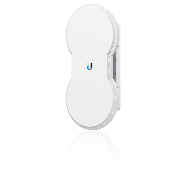
Package Contents
 |
|---|
| airFiber AF-5/AF-5U |
 |
|---|
| I-Bracket |
 |
|---|
| Upper Mount Bracket with Elevation Rod |
 |
|---|
| Lower Mount Bracket |
 |
|---|
| Pole Clamps (Qty. 2) |
 |
|---|
| M10x150 Carriage Bolts (Qty. 4) |
 |
|---|
| M10x100 Carriage Bolts (Qty. 2) |
 |
|---|
| Serrated Flange Bolts (Qty. 4) |
 |
|---|
| Stabilizer Brackets (Qty. 2) |
 |
|---|
| Serrated Flange Nuts (Qty. 6) |
 |
|---|
| Zip Ties (Qty. 2) |
| Gigabit PoE (50V, 1.2A) |
 |
|---|
| Power Cord |
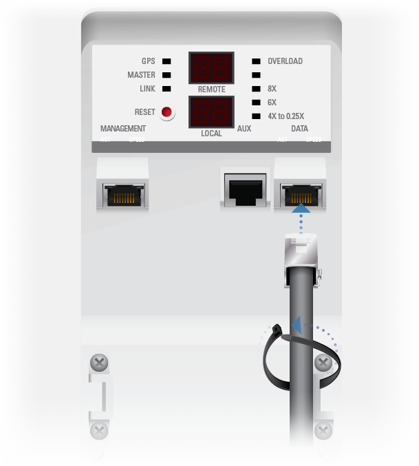
Hardware Overview
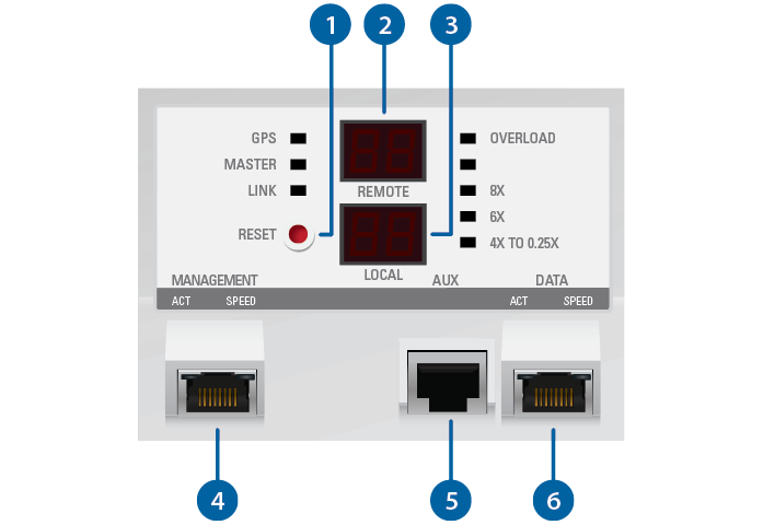
 Reset Button |
|---|
To reset to factory defaults, press and hold the Reset button for more than five seconds while the unit is powered on. |
 Remote Display |
Displays the received signal strength in dBm of the remote airFiber radio. |
 Local Display |
Displays the received signal strength in dBm of the local airFiber radio. |
 Management Port |
10/100 Mbps, secured port for configuration. By default, this is the only port that can monitor, configure, and/or update firmware. |
 Aux Port |
Port for audio tone aiming. |
 Data Port |
10/100/1000 Mbps port handles all user traffic. |
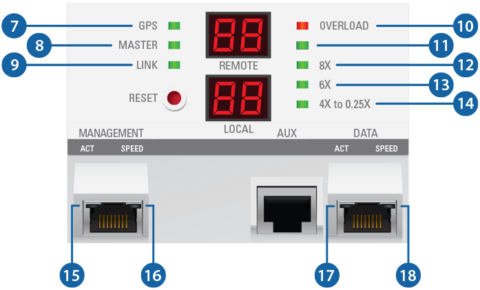

GPS LED |
|
|---|---|
Off |
No GPS synchronization |
On |
Operational (strong signal) |
Normal Flash1 |
Non-operational (weak signal) |

Master LED |
|
Off |
Slave mode |
On |
100 Mbps |

Link LED |
|
Off |
RF off |
Short Flash1 |
Syncing |
Normal Flash1 |
Beaconing |
Long Flash1 |
Registering |
On |
Operational |

Overload LED |
|
Fast Flash |
Overload condition |

(Unlabeled) LED |
|
On |
10x (1024QAM MIMO) |

8x LED |
|
On |
256QAM MIMO |

6x LED |
|
On |
64QAM MIMO |

4x to 0.25x LED |
|
On |
16QAM MIMO |
Long Flash1 |
QPSK MIMO |
Normal Flash1 |
1x QPSK xRT2 |
Short Flash1 |
¼x QPSK xRT2 |

Management Port Activity LED |
|
Off |
No Ethernet link. |
On |
Ethernet link established. |
Random Flashing |
Ethernet activity. |

Management Port Speed LED |
|
Off |
10 Mbps |
On |
100 Mbps |

Data Port Activity LED |
|
Off |
No Ethernet link. |
On |
Ethernet link established. |
Random Flashing |
Ethernet activity. |

Data Port Speed LED |
|
Off |
10/100 Mbps |
On |
1000 Mbps |
1 Short Flash (1:3 on/off cycle), Normal Flash (1:1 on/off cycle), Long Flash (3:1 on/off cycle)
2 xtreme Range Technology
Installation Requirements
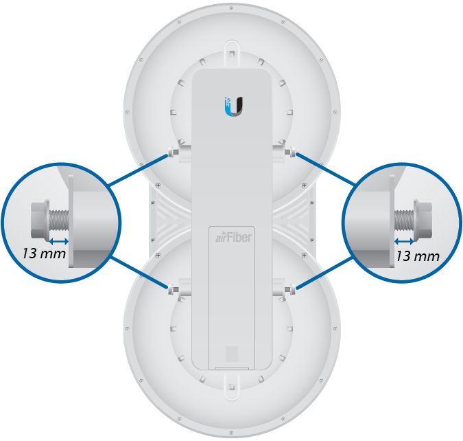
Pre-Assembly Tool
- 13 mm wrench
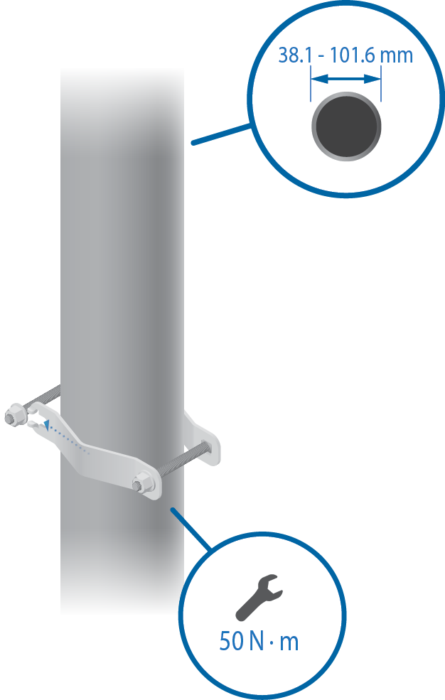
Pole-Mounting Tool
- 17 mm wrench
Other Requirements
- Clear line of sight between airFiber radios
- Clear view of the sky for proper GPS operation
- Vertical mounting orientation
- Mounting location with < 0.5° displacement due to twist and sway under wind loading
- Mounting point:
- At least 1 m below the highest point on the structure
- For tower installations, at least 3 m below the top of the tower
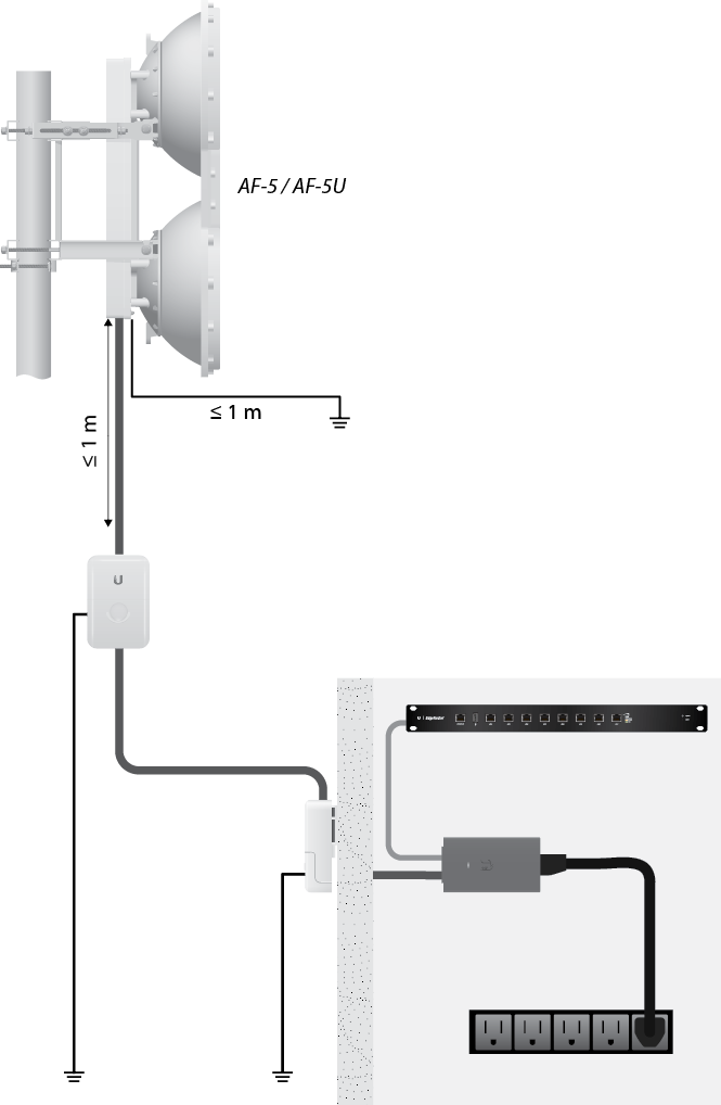
- Ground wires – min. 10 AWG (5 mm2) and max. length: 1 m. As a safety precaution, ground the airFiber radios to grounded masts, poles, towers, or grounding bars.
- (Recommended) 2 Outdoor Gigabit PoE surge protectors
- Outdoor, shielded Category 6 (or above) cabling and shielded RJ45 connectors are required for all wired Ethernet connections.
| WARNING: Failure to properly ground your airFiber units will void your warranty. |
|---|

| Note: For guidelines about grounding and lightning protection, follow your local electrical regulatory codes. |
|---|
Installation Overview
We recommend that you configure your paired airFiber radios before mounting. Below is an overview of the installation with specific details in the following instructions:
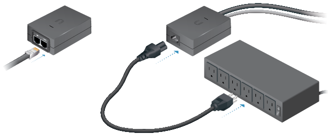
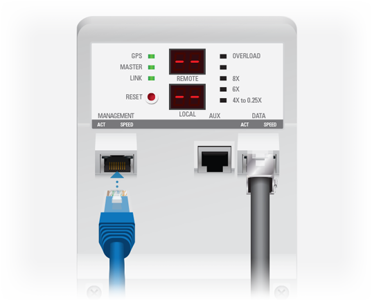
- Connect Power over Ethernet to the Data port, and connect an Ethernet cable between your computer and the Management port.
- Configure the device settings in the airFiber Configuration Interface.
- Once configuration is complete, disconnect the cables to move the airFiber radios.
- Pre-assemble the mounting hardware.
- Install the airFiber radios at the site.
- Establish and optimize the RF link.
|
|
Note: The AF-5 and AF-5U models share the same installation and configuration instructions. |
|---|
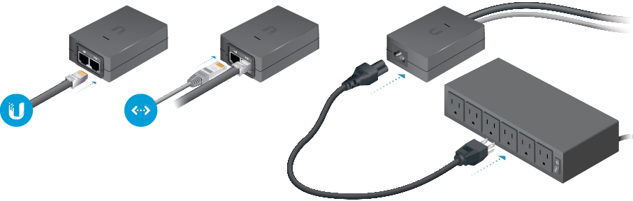
Connecting Power over Ethernet
airFiber Configuration
This section explains how to access the airFiber Configuration Interface and configure the following settings:
- Wireless Mode Configure one airFiber radio as the Master and the other as the Slave.
- Duplex The airFiber radio supports both half-duplex and full-duplex operation. Half-duplex operation provides more frequency planning options at the cost of higher latency and throughput. Full-duplex operation provides the highest throughput and lowest latency; however, you have fewer frequency management options.
- Half Duplex (default) The TX and RX Frequencies can be the same or different to suit local interference.
- Full Duplex The TX and RX Frequencies should be different.
- TX and RX Frequencies The TX Frequency on the Master must match the RX Frequency on the Slave, and vice versa.
- Connect an Ethernet cable from your computer to the Management port on the airFiber radio.
- Configure the Ethernet adapter on your computer with a static IP address on the 192.168.1.x subnet.
- Launch your web browser. Type http://192.168.1.20 in the address field and press enter (PC) or return (Mac).

- The login screen will appear. Enter ubnt in the Username and Password fields. Select your Country and Language. You must agree to the Terms of Use to use the product. Click Login.
- The Main tab will appear. Click the Tools drop-down and select Link Calculator. This tool will guide you on how to best minimize bandwidth and power/interference issues.
- Enter the requirements of your link, and then click Calculate. Adjust the values as needed to get the optimal result, and then write down the settings needed for your configuration.
- Click the Wireless tab.
- Enter the Basic Wireless Settings:
- For one airFiber radio, select Master as the Wireless Mode. For the other airFiber radio, keep the default, Slave.
- Enter a name in the Link Name field. This should be the same on both the Master and the Slave.
- For the Duplex drop-down:
Half Duplex The default mode. The TX and RX Frequencies can be the same or different to suit local interference.
Full Duplex The TX and RX Frequencies should be different.
- Select a TX Frequency. This must match the RX Frequency on your other airFiber radio.
- Select a RX Frequency. This must match the TX Frequency of your other airFiber radio.
- If needed, change the Output Power and/or Maximum Modulation Rate settings.
- Configure the Wireless Security:
- Select the AES Key Type, HEX or ASCII.
- For the Key field:
HEX Enter 16 bytes (eight, 16-bit HEX values: 0-9, A-F, or a-f). You can omit zeroes and use colons, similar to the IPv6 format.

Note: The airFiber Configuration Interface supports IPv6 formats excluding dotted quad and "::" (double-colon) notation.
ASCII Enter a combination of alphanumeric characters (0-9, A-Z, or a-z).
- Click Change and then click Apply.
- In-Band Management is enabled by default, so each airFiber radio must have a unique IP Address. (If the airFiber radios use the same IP Address, you may lose access to the airFiber radios via the Data ports.) Click the Network tab.
- For the Management IP Address option:
DHCP Keep the default, DHCP, to use DHCP reservation on your router to assign a unique IP Address.
Static Change the IP Address, Netmask, and other settings to make them compatible with your network.
- Click Change and then click Apply.
- For the Management IP Address option:
Note: U.S. product versions are locked to the U.S. Country Code to ensure compliance with FCC regulations.
Note: If you do not see the Link Calculator, upgrade the firmware on your airFiber radios. Download the firmware at: ui.com/download/airfiber
- Connect an Ethernet cable from your computer to the Management port on the airFiber radio.
Repeat the instructions in the airFiber Configuration section on your other airFiber radio. After you have configured the airFiber radios, disconnect them and move them to your installation site.
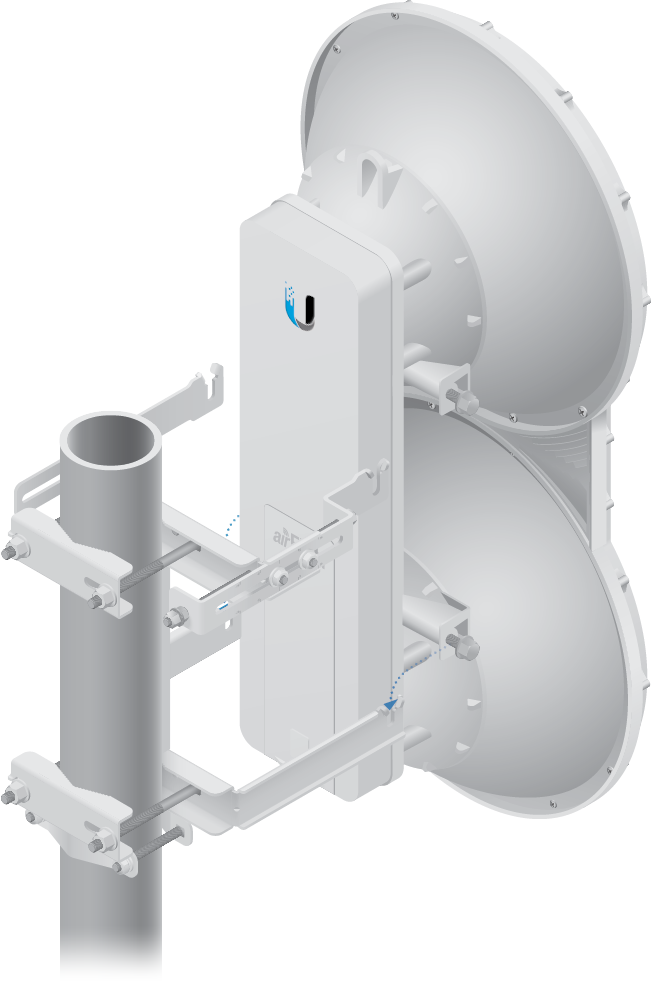
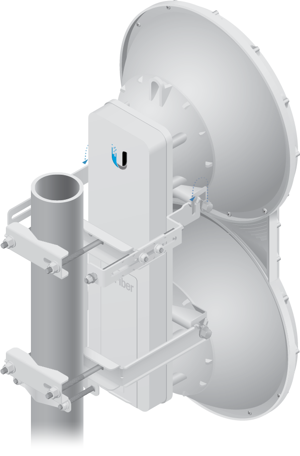
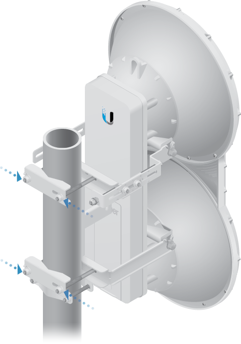
Hardware Installation
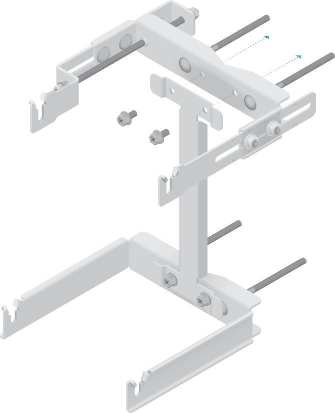
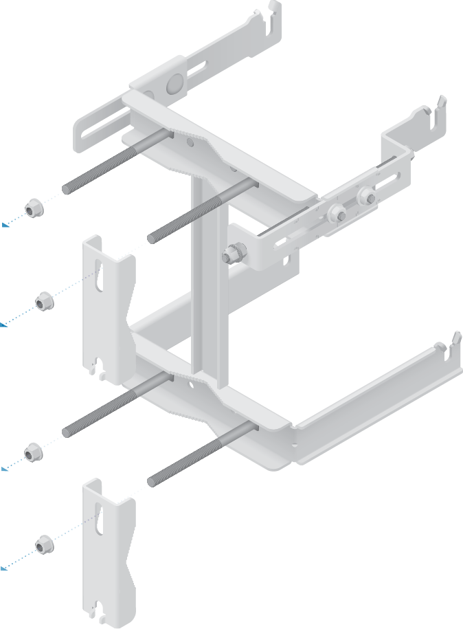
The mounting hardware of the airFiber radio can be pre-assembled before pole-mounting.
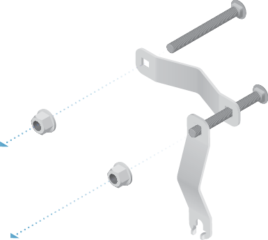
Mounting Hardware Pre-Assembly
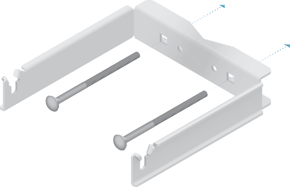
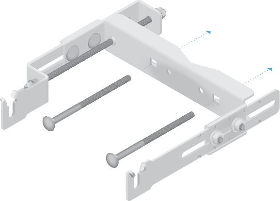
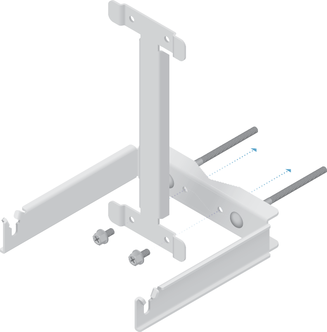
| Note: Ensure that the orientation of the Upper Mount Bracket matches the illustration below, with the Elevation Rod on the correct side. |
|---|
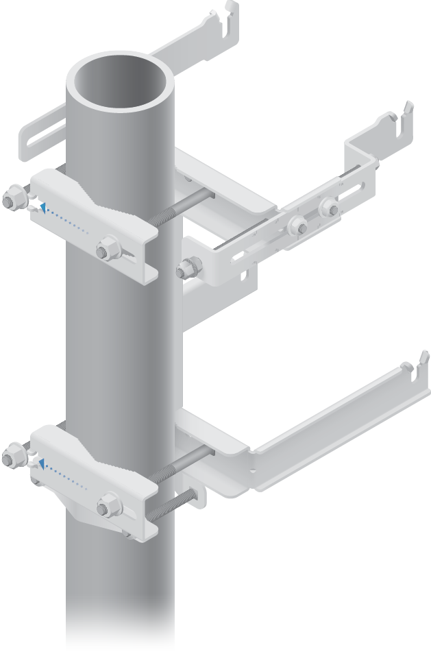
Pole-Mounting
Install a Ground Wire
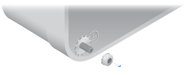
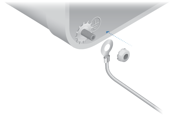
Secure the other end of the ground wire to a grounded mast, pole, tower, or grounding bar.
|
|
WARNING: Failure to properly ground your airFiber units will void your warranty. |
|---|

|
|
Note: The ground wire should be as short as possible and no longer than one meter in length. |
|---|
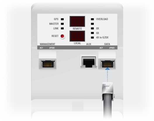
Connecting Ethernet
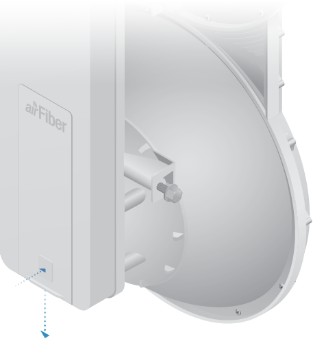
- Feed an outdoor, shielded CAT6 cable up through the rightmost cable feed slot on the bottom of the port cover.
Surge Protection
For added protection, install two surge suppressors, such as the Ubiquiti Ethernet Surge Protector, model ETH-SP, at the end of each link. Install the first surge protector within one meter of the airFiber DATA port, and install the second surge protector at the ingress point of the location housing the wired network equipment.
Alignment
Tips
- To accurately align the airFiber radios for best performance, you MUST align only one end of the link at a time.
- For more convenient alignment, you may consider using long-range scopes (not included) temporarily attached to your airFiber radios.
- You may need to use additional hardware to compensate for issues such as the improper orientation of a mounting pole or significant elevation differences between airFiber radios.
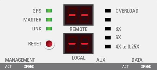
Before a link is established, the Master's LED Display looks like this:
- GPS and Master LEDs are solidly lit
- Link Status LED flashes (Normal Flash 1:1)
- Remote and Local LED Displays show a double dash
| Note: The GPS LED may not be lit if there is a weak GPS signal. A GPS signal is not required for alignment. |
|---|

|
|
Note: The Local LED Display may briefly flash a large number (such as 95) when there is no link. |
|---|
Establishing a Link
Adjust the positions of the Master and the Slave to establish a link.
|
|
Note: The Master must be aimed first at the Slave because the Slave does not transmit any RF signal until it detects transmissions from the Master. |
|---|
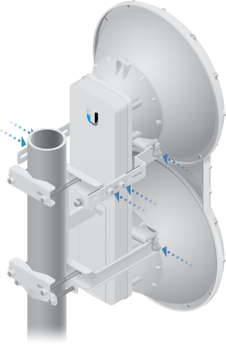
- Ensure that the following bolts and nuts are loose:
- Four Pre-Installed M10x25 Flanged Bolts on the airFiber radio (two on each side)
- Four M10 Hex Nuts used to lock the elevation alignment on the Upper Mount Bracket (two on each side)
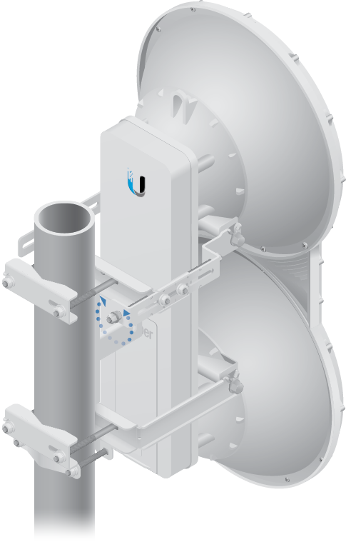
- Ensure that the pole mount fits snugly while keeping the four Serrated Flange Nuts on the Pole Clamps loose enough to allow rotation around the pole for azimuth alignment.
- Master Visually aim the Master at the Slave. To adjust the Master's position:
- Rotate the airFiber radio on the pole to align the azimuth.
- Use the hex nut on the Elevation Rod to adjust the elevation.
- Slave Visually aim the Slave at the Master. To adjust the Slave's position:
- Rotate the airFiber radio on the pole to align the azimuth.
- Use the hex nut on the Elevation Rod to adjust the elevation.
- Check to see if a link is established. Ensure that the Link Status LED is solidly lit green and the Remote and Local LED Displays of the Slave are displaying signal levels.
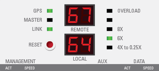
- Slave Aim the Slave at the Master to achieve the strongest signal level on the Remote LED Display of the Slave.
Note: Values on the LED Displays are displayed in negative (-) dBm. For example, 67 represents a received signal level of -67 dBm. Smaller numerical values indicate stronger received signal levels. For example, a reading of 49 is stronger than a reading of 55.
Note: Maximum signal strength can best be achieved by iteratively sweeping through both azimuth and elevation.
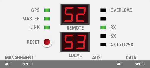
- Master Aim the Master at the Slave to achieve the strongest signal level on the Remote LED Display of the Master.
Note: If the Overload LED lights up, refer to the airFiber AF-5/AF-5U User Guide at: ui.com/download/airfiber
- Repeat steps 6 and 7 until you achieve a symmetric link, with the signal levels within 1 dB of each other. This ensures the best possible data rate between the airFiber radios.
- Lock the alignment on both airFiber radios by tightening the nuts and bolts.
- Observe the Local and Remote LED Displays of each airFiber radio to ensure that the values remains constant while tightening the nuts and bolts. If any LED value changes during the locking process, loosen the nuts and bolts, finalize the alignment of each airFiber radio again, and retighten the nuts and bolts.
- For each airFiber radio, close the port cover and ensure that the Ethernet cable stays in the cable feed slot.
|
|
Note: Do NOT make simultaneous adjustments on the Master and Slave. |
|---|
There are three methods for determining the received signal level:
- LED Displays (described above)
- airFiber Configuration Interface (webpage)
- Audio tone (optional equipment required)
Refer to the airFiber AF-5/AF-5U User Guide for instructions on the airFiber Configuration Interface and audio tone methods.
Installer Compliance Responsibility
Devices must be professionally installed and it is the professional installer’s responsibility to make sure the device is operated within local country regulatory requirements.
The Frequency and Output Power fields are provided to the professional installer to assist in meeting regulatory requirements.
Specifications
|
airFiber AF-5/AF-5U |
|
|
Dimensions |
938.4 x 468.4 x 281.4 mm (36.94 x 18.44 x 11.08") |
|---|---|
|
Weight |
|
| Mount Not Included | 11.5 kg (25.35 lb) |
| Mount Included | 16 kg (35.27 lb) |
|
Operating Frequency AF-5 |
|
| FCC 15.247, 15.407, IC RSS 210 | 5470 - 5600 MHz, 5650 - 5850 MHz |
| ETSI EN 301 893, EN 302 502 | 5470 - 5875 MHz |
| Other Regions | 5470 - 5950 MHz |
| AF-5U | |
| FCC 15.247, IC RSS 21 | 5725 - 5850 MHz |
| ETSI EN 302 502 | 5725 - 5875 MHz |
| Other Regions | 5725 - 6200 MHz |
|
Max. Power Consumption |
40W |
|
Power Supply |
50V, 1.2A Gigabit PoE Adapter (Included) |
|
Power Method |
Passive Power over Ethernet |
|
Mounting |
Pole Mount Kit (Included) |
|
Wind Loading |
863 N @ 200 km/hr (194 lbf @ 125 mph) |
|
Wind Survivability |
200 km/hr (125 mph) |
|
Operating Temperature |
-40 to 55° C (-40 to 131° F) |
|
Certifications |
CE, FCC, IC |
|
Networking Interface |
|
| Data Port | (1) 10/100/1000 Ethernet Port |
| Management Port | (1) 10/100 Ethernet Port |