Package Contents
 |
|---|
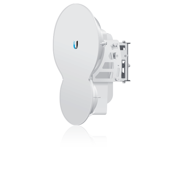
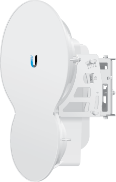
| airFiber AF-24 |
 |
|---|
| Pole Mount Bracket |
 |
|---|
| Pole Clamps (Qty. 2) |
 |
|---|
| Zip Ties (Qty. 3) |
 |
|---|
| Carriage Bolts (Qty. 3) |
 |
|---|
| Flat Washers (Qty. 4) |
 |
|---|
| Split Lock Washers (Qty. 4) |
 |
|---|
| Hex Nuts (Qty. 4) |
 |
|---|
| Gigabit PoE Adapter (50V, 1.2A) |
 |
|---|
| Power Cord |
Hardware Overview
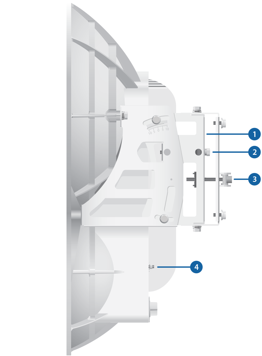
 Alignment Bracket |
|---|
 Elevation Adjustment |
 Azimuth Adjustment |
 Ground Bonding Point |
 Lock Bolts |
 Port Cover |
 Cover Lock |
LEDs, Ports, and Display
|
Speed LED (Data Port) |
||||||||
|---|---|---|---|---|---|---|---|---|
Off |
10/100 Mbps |
|||||||
On |
1000 Mbps |
|||||||
|
Link/Activity LED (Data Port) |
||||||||
Off |
No Ethernet Link |
|||||||
On |
Ethernet Link Established |
|||||||
Random Flashing |
Ethernet Activity |
|||||||
|
GPS LED (Auxiliary Port) |
||||||||
Off |
No GPS Synchronization |
|||||||
On |
Operational (Strong Signal) |
|||||||
Normal Flash* |
Operational (Weak Signal) |
|||||||
|
Modulation LED (Auxiliary Port) |
||||||||
Off |
¼x or 1x (QPSK SISO) |
|||||||
Short Flash* |
2x (QPSK MIMO) |
|||||||
Normal Flash* |
4x (16QAM MIMO) |
|||||||
Long Flash* |
6x (64QAM MIMO) |
|||||||
|
Master/Slave LED |
||||||||
Off |
Slave Mode |
|||||||
On |
Master Mode |
|||||||
|
RF Link Status LED |
||||||||
Off |
RF Off |
|||||||
Short Flash* |
Syncing |
|||||||
Normal Flash* |
Beaconing |
|||||||
Long Flash* |
Registering |
|||||||
On |
Operational |
|||||||
|
Speed LED (Configuration Port) |
||||||||
Off |
10 Mbps |
|||||||
On |
100 Mbps |
|||||||

Link/Activity LED (Configuration Port) |
||||||||
Off |
No Ethernet Link |
|||||||
On |
Ethernet Link Established |
|||||||
Random Flashing |
Ethernet Activity |
|||||||

Reset Button |
||||||||
To reset to factory defaults, press and hold the Reset button for more than five seconds while the unit is powered on. |
||||||||

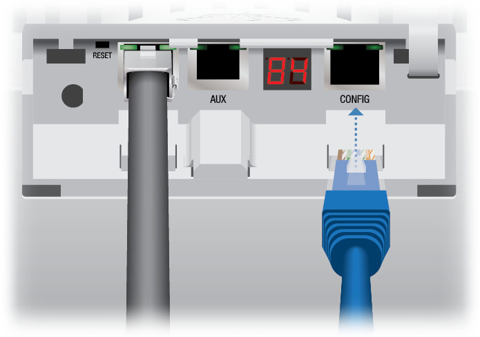
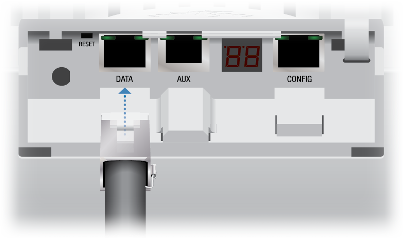
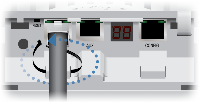
Data Port |
||||||||
10/100/1000 Mbps port handles all user traffic. |
||||||||

Auxiliary Port |
||||||||
Port for audio tone aiming. |
||||||||

LED Display |
||||||||
Digital display used for power, status, and mode information.
|
||||||||

Configuration Port |
||||||||
10/100 Mbps, secured port for configuration. By default, this is the only port that can monitor, configure, and/or update firmware. |
||||||||

* Short Flash (1:3 on/off cycle)
Normal Flash (1:1 on/off cycle)
Long Flash (3:1 on/off cycle)
Installation Requirements
- 17 mm wrench
- 13 mm socket wrench or driver
- Clear line of sight between airFiber radios
- Clear view of the sky for proper GPS operation
- Mounting location with < 0.5° displacement due to twist and sway under wind loading
- Mounting point:
- At least 1 meter below the highest point on the structure
- For tower installations, at least 3 meters below the top of the tower
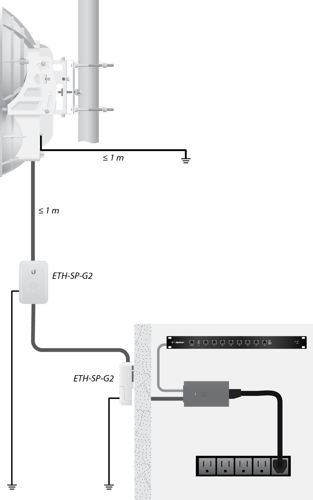
- Ground wires – min. 8 AWG (10 mm2) and max. length: 1 meter. As a safety precaution, ground the airFiber radios to grounded masts, poles, towers, or grounding bars.
- (Recommended) 2 Outdoor GigE PoE surge protectors
- Outdoor, shielded Category 5e (or above) cabling and shielded RJ-45 connectors should be used for all wired Ethernet connections. Category 6 is required for installations with long cable runs (up to 100 m).
We recommend that you protect your networks from harmful outdoor environments and destructive ESD events with industrial-grade, shielded Ethernet cable from Ubiquiti. For more details, visit ui.com/toughcable
| WARNING: Failure to properly ground your airFiber units will void your warranty. |
|---|

| Note: For guidelines about grounding and lightning protection, follow your local electrical regulatory codes. |
|---|
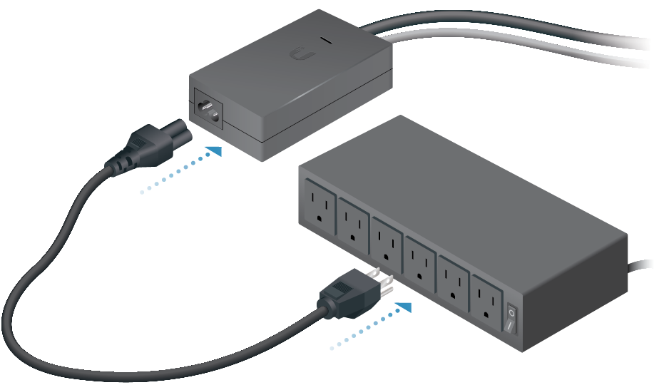
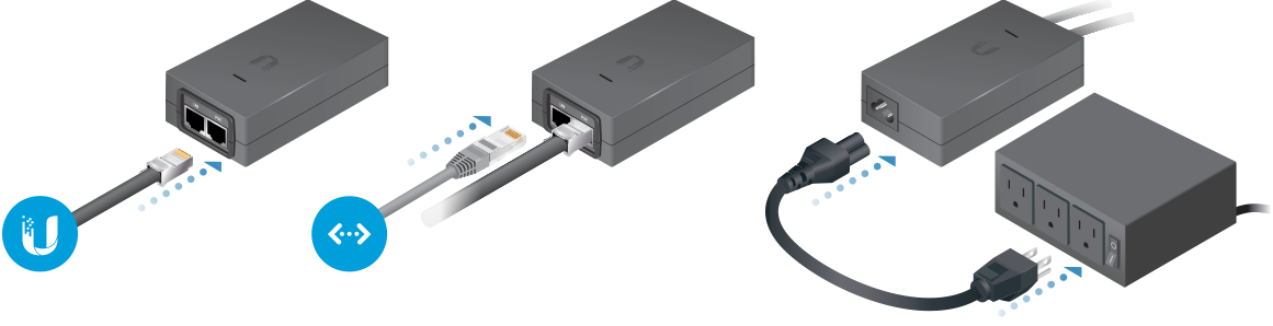
Connecting Power over Ethernet

airFiber Configuration
The instructions in this section explain how to access the airFiber Configuration Interface and configure the following settings:
- Wireless Mode Configure one airFiber AF-24 as the Master and the other as the Slave.
- Duplex The airFiber AF-24 supports both half-duplex and full-duplex operation. Half-duplex operation provides more frequency planning options at the cost of higher latency and throughput. Full-duplex operation provides the highest throughput and lowest latency; however, you have fewer frequency management options.
- Half Duplex (default) The TX and RX Frequencies can be the same or different to suit local interference.
- Full Duplex The TX and RX Frequencies should be different.
- TX and RX Frequencies The TX Frequency on the Master must match the RX Frequency on the Slave, and vice versa.
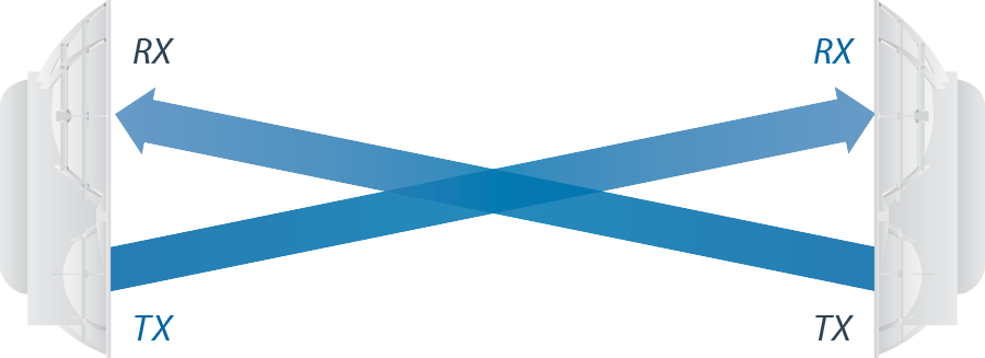
Half-Duplex Diagram

Full-Duplex Diagram
- Connect an Ethernet cable from your computer to the Config port on the airFiber AF-24.
- Configure the Ethernet adapter on your computer with a static IP address on the 192.168.1.x subnet (for example, 192.168.1.100).
- Launch your web browser. Type http://192.168.1.20 in the address field and press enter (PC) or return (Mac).

- Enter ubnt in the Username and Password fields. Select your Country and Language. You must agree to the Terms of Use to use the product. Click Login.

Note: U.S. product versions are locked to the U.S. Country Code to ensure compliance with FCC regulations.
- Click the Wireless tab.
- Enter the Basic Wireless Settings:
- For one airFiber AF-24, select Master from the Wireless Mode drop-down. For the other airFiber AF-24, keep the default, Slave.
- Enter a name in the Link Name field. This should be the same on both the Master and the Slave.
- For the Duplex drop-down:
- Half Duplex The default mode. The TX and RX Frequencies can be the same or different to suit local interference.
- Full Duplex The TX and RX Frequencies should be different.
- Select a TX Frequency. This must match the RX Frequency of your other airFiber AF-24.
- Select a RX Frequency. This must match the TX Frequency of your other airFiber AF-24.
- If needed, change the Output Power, Maximum Modulation Rate, and/or RX Gain settings.
- Configure the Wireless Security:
- Select the AES Key Type, HEX or ASCII.
- For the Key field:
- HEX Enter 16 bytes (eight, 16-bit HEX values: 0-9, A-F, or a-f). You can omit zeroes and use colons, similar to the
IPv6 format.Note: The airFiber Configuration Interface supports IPv6 formats excluding dotted quad and "::" (double-colon) notation.
- ASCII Enter a combination of alphanumeric characters (0-9, A-Z, or a-z).
- HEX Enter 16 bytes (eight, 16-bit HEX values: 0-9, A-F, or a-f). You can omit zeroes and use colons, similar to the
- Click Change and then click Apply.
- In-Band Management is enabled by default, so each airFiber radio must have a unique IP Address. (If the airFiber radios use the same IP Address, then you may lose access to the airFiber radios via the Data ports.) To change the network settings:
- Click the Network tab.
- Change the IP Address, Netmask, and other settings to make them compatible with your network.
- Click Change and then click Apply.
Repeat the instructions in the airFiber Configuration section on your other airFiber radio. After you have configured the airFiber radios, disconnect them and move them to your installation site.
Hardware Installation
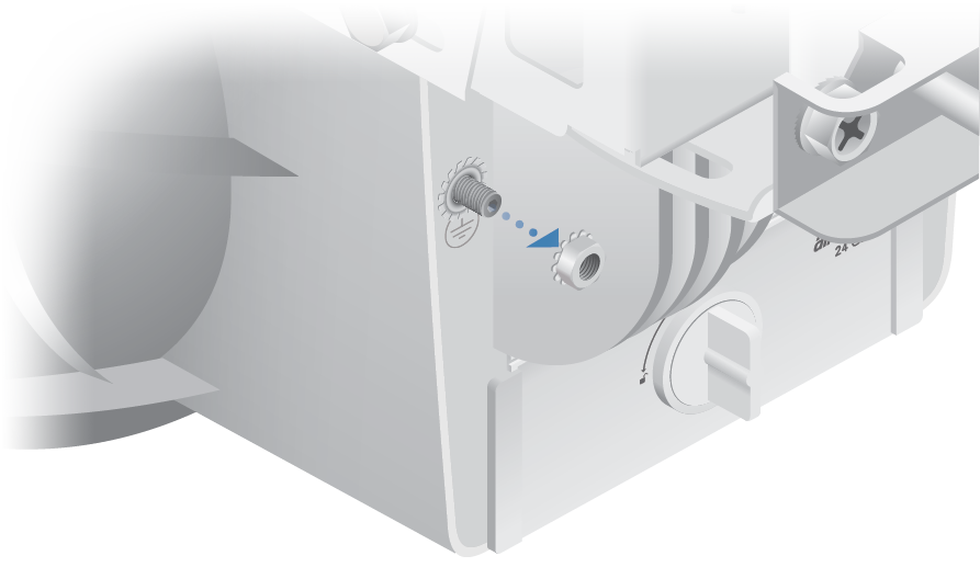
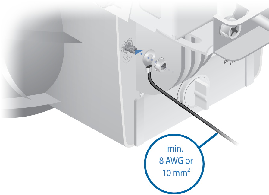
- Secure the other end of the ground wire to a grounded mast, pole, tower, or grounding bar.
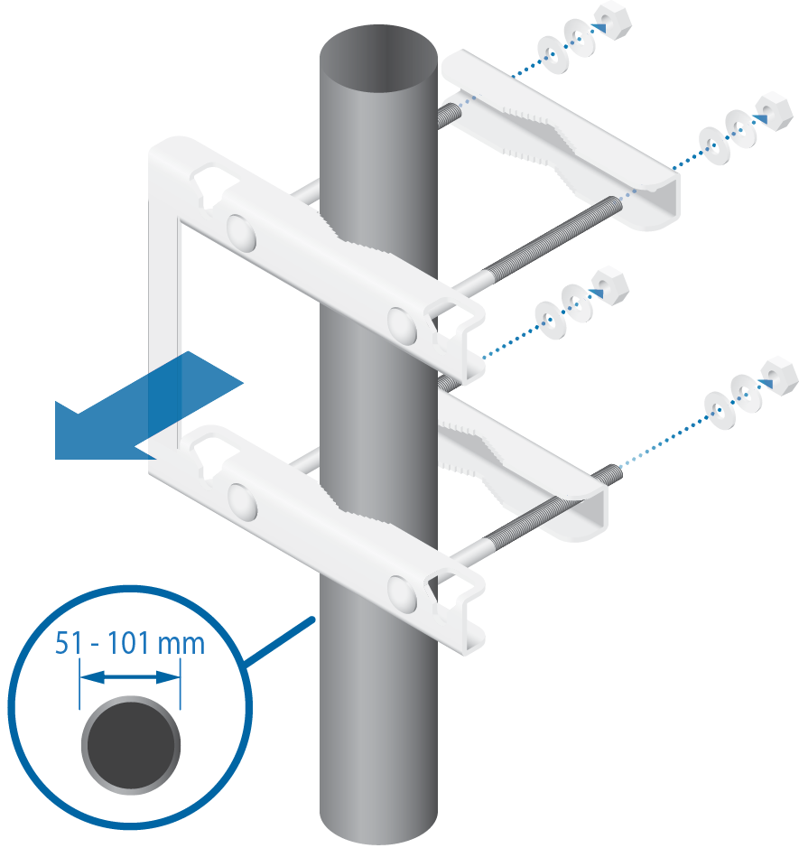
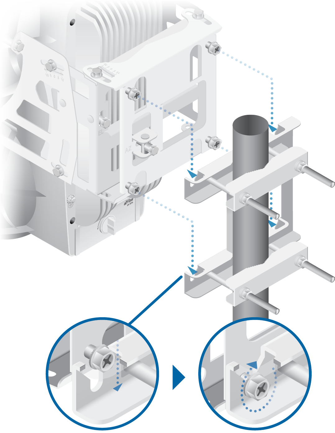
| Note: Orient the Pole Mount Bracket around the pole so it is aimed in the direction of the other airFiber AF-24. |
|---|
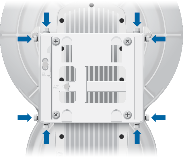
| Note: Loosen, but do NOT remove the eight Lock Bolts located on the Alignment Bracket. |
|---|
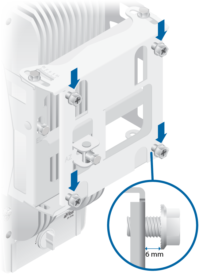
| WARNING: To prevent injury, ensure that all four screws are seated and fully tightened. |
|---|
| WARNING: Failure to properly ground your airFiber units will void your warranty. |
|---|
| Note: The ground wire should be as short as possible and no longer than one meter in length. |
|---|
Connecting Ethernet
|
|
Note: For added protection, we recommend installing two GigE PoE surge protectors. Install the first surge protector within one meter of the airFiber Data port, and install the second surge protector at the ingress point of the location housing the wired network equipment. |
|---|
Below is a diagram of a finished installation with recommended surge protectors installed.
Alignment
Tips
- Fine-tuning is best achieved by a pair of installers with a dedicated, two-way communication link: one installer makes adjustments on one airFiber radio while the other installer reports the received signal level at the other airFiber radio. Fine-tuning (see "Fine-Tuning the Link") is necessary because the main lobe of the receiver is narrower than that of the transmitter, in both azimuth and elevation.
- To accurately align the airFiber radios for best performance, you MUST align only one end of the link at a time.
- For more convenient alignment, you may consider using long-range scopes (not included) temporarily attached to your airFiber radios.
- You may need to use additional hardware to compensate for issues such as the improper orientation of a mounting pole or significant elevation differences between the airFiber radios.
Establishing a Preliminary Link
Adjust the positions of the Master and the Slave to establish a preliminary link. This requires the Master and Slave to be within a few degrees of the line of sight between the airFiber radios.
|
|
Note: The Master must be aimed first at the Slave because the Slave does not transmit any RF signal until it detects transmissions from the Master. |
|---|
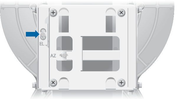
- For the Master and Slave, ensure the eight Lock Bolts on the Alignment Bracket are sufficiently loose by spinning each washer by hand.
- For the Master and Slave, ensure the Azimuth (AZ) and Elevation (EL) Adjustment Bolts are in the middle of their adjustment ranges.
- Master Aim the Master at the Slave. If necessary, adjust the Master's position on the pole:
- Loosen the Hex Nuts.
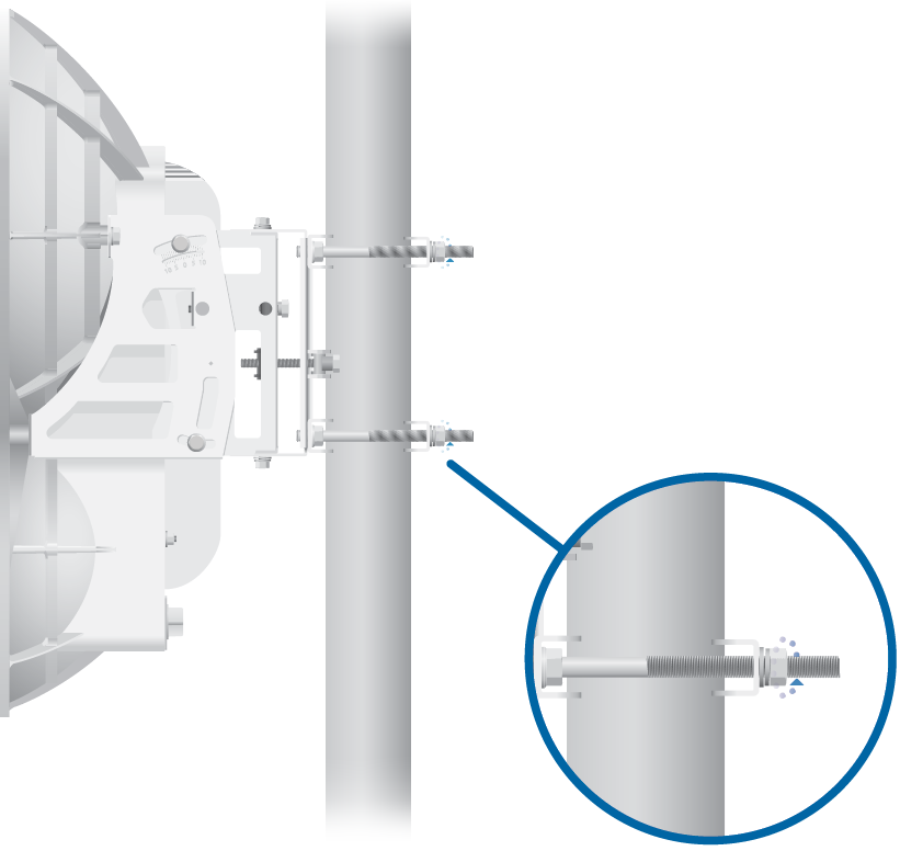
- Adjust the Pole Mount Bracket and Pole Clamps.
- Tighten the Hex Nuts.
- Loosen the Hex Nuts.
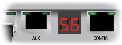
- Slave Aim the Slave at the Master to achieve the strongest received signal level on the Slave's numeric LED Display, which is located next to the Config port. If necessary, adjust the Slave's position on the pole.
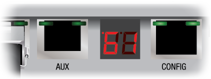
Note: Values on the LED Display are displayed in negative (-) dBm. For example, 61 represents -61 dBm, which is stronger than -72 dBm.
- Master Adjust the azimuth and elevation of the Master until the strongest received signal level is displayed on the LED Display of the Master.
- Sweep the Azimuth (AZ) Adjustment Bolt of the Master through its adjustment range.

- Sweep the Elevation (EL) Adjustment Bolt of the Master through its adjustment range.
- Sweep the Azimuth (AZ) Adjustment Bolt of the Master through its adjustment range.
| WARNING: All Lock Bolts MUST be loose to avoid damage to the airFiber housing. |
|---|
|
|
Note: If the LED Display indicates an overload condition |
|---|
 , refer to the airFiber AF-24 User Guide at:
 Fine-Tuning the Link
The Azimuth (AZ) and Elevation (EL) Adjustment Bolts of the Alignment Bracket adjust the azimuth and elevation within a range of ±10°. For accurate alignment, make adjustments on one end of the link while the other installer reports the received signal level at the other end of the link. Do NOT make simultaneous adjustments on the Master and Slave.
- Slave Adjust the azimuth and elevation of the Slave until the other installer sees the strongest received signal level displayed on the LED Display of the Master.
- Master Adjust the azimuth and elevation of the Master until the other installer sees the strongest received signal level displayed on the LED Display of the Slave.
- Repeat steps 1 and 2 until you achieve a symmetric link, with the received signal levels within 1 dB of each other. This ensures the best possible data rate between the airFiber radios.
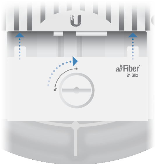
- Lock the alignment on both airFiber radios by tightening all eight Lock Bolts on the Alignment Bracket.
- Observe the LED Display of each airFiber AF-24 to ensure that the value remains constant while tightening the Lock Bolts. If the LED value changes during the locking process, loosen the Lock Bolts, finalize the alignment of each airFiber AF-24 again, and retighten the Lock Bolts.
- For each airFiber AF-24, attach the Port Cover and turn the Cover Lock to the Locked
 icon.
icon.
There are three methods for determining the received signal level:
- LED Display (described above)
- airFiber Configuration Interface
- Audio tone (optional equipment required)
Refer to the airFiber AF-24 User Guide for instructions on the airFiber Configuration Interface and audio tone methods. The User Guide is available at: ui.com/download/airfiber
Installer Compliance Responsibility
Devices must be professionally installed and it is the professional installer's responsibility to make sure the device is operated within local country regulatory requirements.
The TX Frequency, RX Frequency, and Output Power fields are provided to the professional installer to assist in meeting regulatory requirements.
Specifications
|
airFiber AF-24 |
|
|
Dimensions |
649 x 426 x 303 mm (25.55 x 16.77 x 11.93") |
|---|---|
|
Weight |
10.5 kg (23.15 lb) Mount Included |
|
Operating Frequency |
24.05 – 24.25 GHz |
|
Power Supply |
50V, 1.2A PoE GigE Adapter (Included) |
|
Power Method |
Passive Power over Ethernet (42-58VDC) |
|
Max Power Consumption |
< 50W |
|
Networking Interface |
|
| Data Port | (1) 10/100/1000 Ethernet Port |
| Configuration Port | (1) 10/100 Ethernet Port |
|
Integrated Split Antenna |
|
| TX Gain | 33 dBi |
| RX Gain | 38 dBi |
|
Mounting |
Pole Mount Kit (Included) |
|
Wind Loading |
306.9 N @ 200 km/hr (69 lbf @ 100 mph) |
|
Operating Temperature |
-40 to 55° C (-40 to 131° F) |
|
Certifications |
CE, FCC, IC |
|
Receive Sensitivity |
|||
|
Modulation |
Sensitivity |
FDD Capacity* |
TDD Capacity* |
|---|---|---|---|
|
64QAM |
-66 dBm |
1500 Mbps |
760 Mbps |
|
16QAM |
-72 dBm |
1000 Mbps |
507 Mbps |
|
QPSK MIMO |
-78 dBm |
500 Mbps |
253 Mbps |
|
QPSK SISO |
-80 dBm |
250 Mbps |
127 Mbps |
|
¼x QPSK SISO |
-87 dBm |
62.5 Mbps |
31.7 Mbps |
* FDD = (2) 100 MHz channels and TDD = (1) 100 MHz channel
Safety Notices
- Read, follow, and keep these instructions.
- Heed all warnings.
- Only use attachments/accessories specified by the manufacturer.
| WARNING: Do not use this product in location that can be submerged by water. |
|---|

| WARNING: Avoid using this product during an electrical storm. There may be a remote risk of electric shock from lightning. |
|---|
Electrical Safety Information
- Compliance is required with respect to voltage, frequency, and current requirements indicated on the manufacturer’s label. Connection to a different power source than those specified may result in improper operation, damage to the equipment or pose a fire hazard if the limitations are not followed.
- There are no operator serviceable parts inside this equipment. Service should be provided only by a qualified service technician.
- This equipment is provided with a detachable power cord which has an integral safety ground wire intended for connection to a grounded safety outlet.
- Do not substitute the power cord with one that is not the provided approved type. Never use an adapter plug to connect to a 2-wire outlet as this will defeat the continuity of the grounding wire.
- The equipment requires the use of the ground wire as a part of the safety certification, modification or misuse can provide a shock hazard that can result in serious injury or death.
- Contact a qualified electrician or the manufacturer if there are questions about the installation prior to connecting the equipment.
- Protective earthing is provided by Listed AC adapter. Building installation shall provide appropriate short-circuit backup protection.
- Protective bonding must be installed in accordance with local national wiring rules and regulations.
Limited Warranty
The limited warranty requires the use of arbitration to resolve disputes on an individual basis, and, where applicable, specify arbitration instead of jury trials or class actions.
Compliance
FCC
Changes or modifications not expressly approved by the party responsible for compliance could void the user’s authority to operate the equipment.
This device complies with Part 15 of the FCC Rules. Operation is subject to the following two conditions.
- This device may not cause harmful interference, and
- This device must accept any interference received, including interference that may cause undesired operation.
This equipment has been tested and found to comply with the limits for a Class A digital device, pursuant to part 15 of the FCC Rules. These limits are designed to provide reasonable protection against harmful interference when the equipment is operated in a commercial environment. This equipment generates, uses, and can radiate radio frequency energy and, if not installed and used in accordance with the instruction manual, may cause harmful interference to radio communications. Operations of this equipment in a residential area is likely to cause harmful interference in which case the user will be required to correct the interference at his own expense.
This radio transmitter (FCC ID: SWX-AF24) has been approved by FCC to operate with the antenna types listed below with the maximum permissible gain and required antenna impedance for each antenna type indicated. Antenna types not included in this list, having a gain greater than the maximum gain indicated for that type, are strictly prohibited for use with this device.
- Antenna Information: Dish antenna, TX Gain: 33 dBi, RX Gain: 38 dBi
ISED Canada
CAN ICES-3(A)/NMB-3(A)
This device complies with ISED Canada licence-exempt RSS standard(s). Operation is subject to the following two conditions:
- This device may not cause interference, and
- This device must accept any interference, including interference that may cause undesired operation of the device.
This radio transmitter (IC: 6545A-AF24) has been approved by ISED Canada to operate with the antenna types listed below with the maximum permissible gain and required antenna impedance for each antenna type indicated. Antenna types not included in this list, having a gain greater than the maximum gain indicated for that type, are strictly prohibited for use with this device.
- Antenna Information: Dish antenna, TX Gain: 33 dBi, RX Gain: 38 dBi
CAN ICES-3(A)/NMB-3(A)
Le présent appareil est conforme aux CNR d’ISDE Canada applicables aux appareils radio exempts de licence. L’exploitation est autorisée aux deux conditions suivantes :
- l’appareil ne doit pas produire de brouillage;
- l’appareil doit accepter tout brouillage radioélectrique subi, même si le brouillage est susceptible d’en compromettre le fonctionnement.
Le présent émetteur radio (IC : 6545A-AF24) a été approuvé par ISDE Canada pour l’exploitation avec l’antenne types énumérés ci-dessous avec le gain maximal admissible et requis l’impédance de l’antenne pour chaque type d’antenne indiqué. Types d’antenne non inclus dans cette liste, ayant un gain supérieur au gain maximal indiqué pour ce type, sont strictement interdits pour une utilisation avec cet appareil.
- Informations d’antenne : Antenne parabolique, Gain TX : 33 dBi, Gain RX : 38 dBi
IMPORTANT NOTE
Radiation Exposure Statement
- This equipment complies with radiation exposure limits set forth for an uncontrolled environment.
- This equipment should be installed and operated with minimum distance 107 cm between the radiator and your body.
- This transmitter must not be co-located or operating in conjunction with any other antenna or transmitter.
AVIS IMPORTANT
Déclaration sur l’exposition aux rayonnements
- Cet équipement est conforme aux limites prévues pour l’exposition aux rayonnements dans un environnement non contrôlé.
- Lors de l’installation et de la mise en fonctionnement de l’équipement, assurez-vous qu’il y ait une distance minimale de 107 cm entre l’élément rayonnant et vous.
- Cet émetteur ne doit être installé à proximité d’aucune autre antenne ni d’aucun autre émetteur, et ne doit être utilisé conjointement à aucun autre de ces appareils.
Australia and New Zealand
| Warning: This equipment is compliant with Class A of CISPR 32. In a residential environment this equipment may cause radio interference. |
|---|

Brazil
| Nota: Este equipamento não tem direito à proteção contra interferência prejudicial e não pode causar interferência em sistemas devidamente autorizados. |
|---|

CE Marking
CE marking on this product represents the product is in compliance with all directives that are applicable to it.
![]()
Country List | ||||||||||||||||||||||||||||||||
| ||||||||||||||||||||||||||||||||
BFWA (Broadband Fixed Wireless Access) members noted in blue |
| Note: This device meets Max. TX power limit per ETSI regulations. |
|---|
The following apply to products that operate in the 5 GHz frequency range:
| Note: This device is restricted to indoor use only when operating in the 5150 - 5350 MHz frequency range within all member states. |
|---|
| Note: All countries listed may operate at 30 dBm. BFWA member states may operate at 36 dBm. |
|---|
| Note: Operation in the 5.8 GHz frequency band is prohibited in BFWA member states. Other countries listed may use the 5.8 GHz frequency band. |
|---|