Package Contents
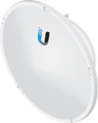 |
|---|
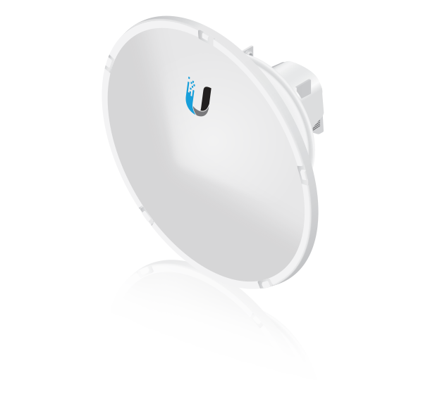
| airFiber AF-11G35 |
 |
|---|
| Shroud |
 |
|---|
| I-Bracket |
 |
|---|
| Upper Mount Bracket with Elevation Rod |
 |
|---|
| Lower Mount Bracket |
 |
|---|
| Pole Clamps (Qty. 2) |
 |
|---|
| Azimuth Support Brackets (Qty. 2) |
 |
|---|
| RF Cables (Qty. 2) |
 |
|---|
| Large Carriage Bolts (Qty. 4) |
 |
|---|
| Small Carriage Bolts (Qty. 2) |
 |
|---|
| Serrated Flange Bolts (Qty. 4) |
 |
|---|
| Bolts with Washers (Qty. 4) |
 |
|---|
| Serrated Flange Nuts (Qty. 6) |
Antenna Compatibility
The airFiber AF-11G35 antenna is designed for use with the airFiber radio model AF-11*.
* Check your local/regional regulations for the allowable antenna gain allowed for your application.
Installation Requirements
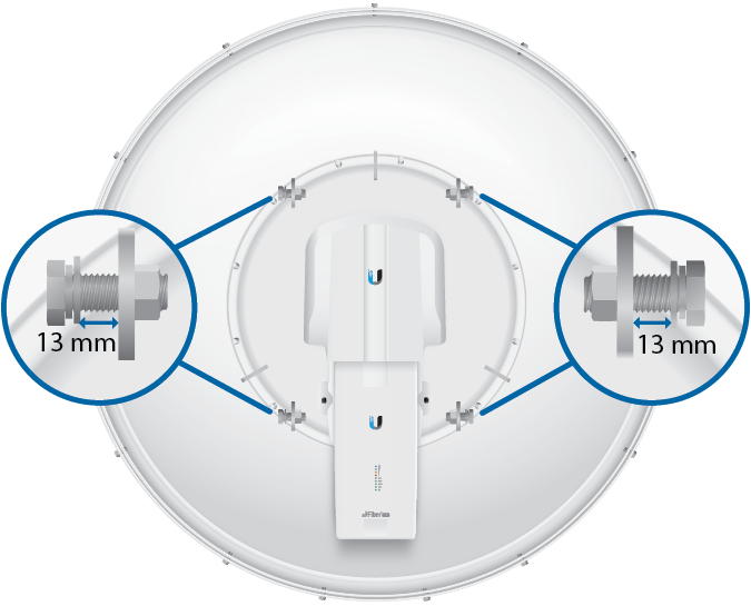
- 12 mm, 15 mm, and 17 mm wrench (pre-assembly and pole-mounting tool)
- airFiber AF-11 radio (sold separately) with duplexer(s) installed
- Clear line of sight between airFiber radios
- Vertical mounting orientation
- Mounting point:
- At least 1 m below the highest point on the structure
- For tower installations, at least 3 m below the top of the tower
- Ground wires – min. 10 AWG (5 mm2) and max. length: 1 m. As a safety precaution, ground the airFiber radios to grounded masts, poles, towers, or grounding bars.

WARNING: Failure to properly ground your airFiber radio will void your warranty.
- (Recommended) 2 Outdoor Gigabit PoE surge protectors

Note: For guidelines about grounding and
lightning protection, follow your local electrical regulatory codes. - (Optional) If not using PoE: DC power source and 12/30 AWG power cable.
- Outdoor, shielded Category 6 (or above) cabling and shielded RJ-45 connectors are required for all wired Ethernet connections.
Hardware Overview
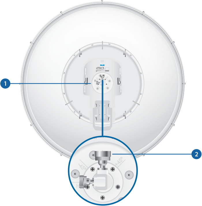

OMT (OrthoMode Transducer) |
|---|
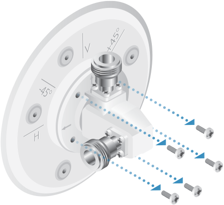
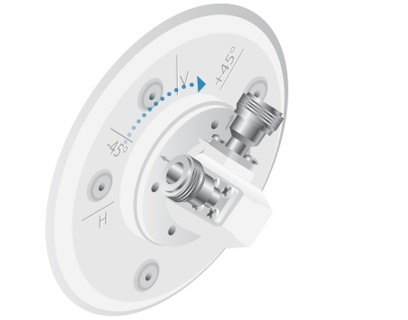
The OMT has two ports used to attach the RF cable(s) from the radio. The OMT is also used to change the polarization from H/V to ± 45º. |

Metal Cap |
For SISO mode, this cap must be installed on the unused OMT port. |
OMT
The OMT (OrthoMode Transducer) is located on the back of the antenna. The default polarization is H and V.
|
|
Note: If you only need to use one port, keep the other one covered with the included Metal Cap. |
|---|
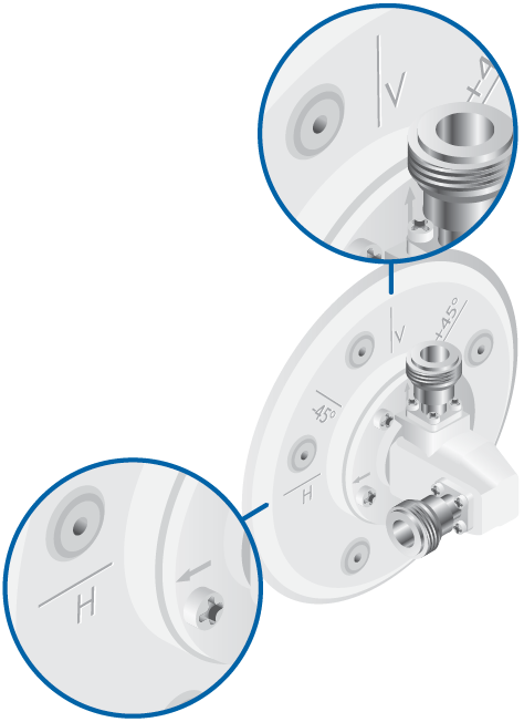
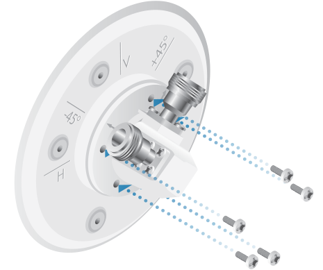
To use ±45° slant polarization:
|
|
Note: ±45° slant polarization is not permitted in all regulatory regions. Please consult local regulations. |
|---|
Hardware Installation
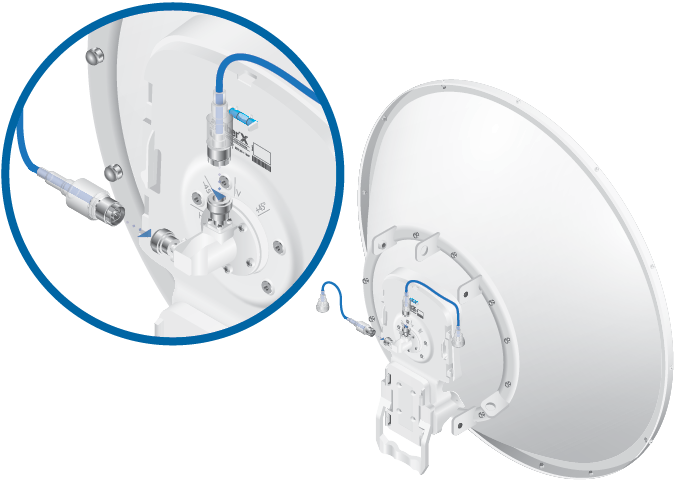
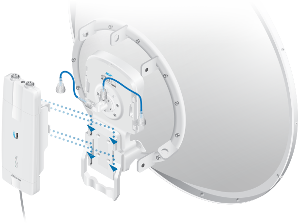
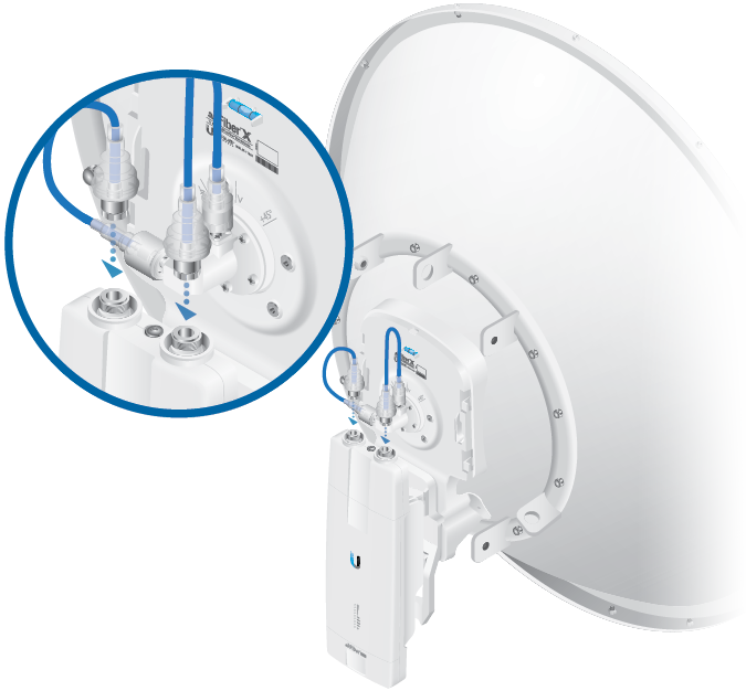
- Connect the RF Cable(s) (one in SISO mode, two in MIMO mode) to the radio as shown below.
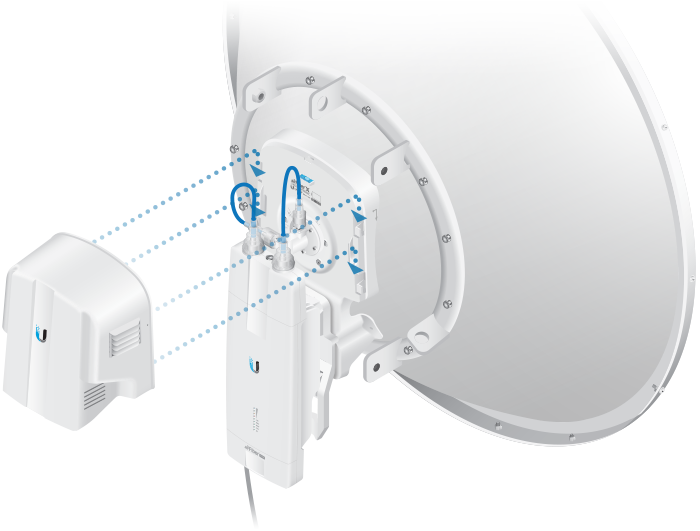
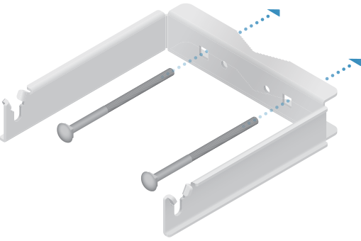
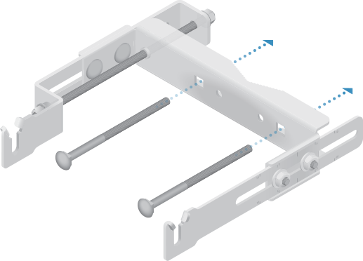
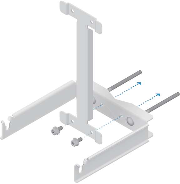
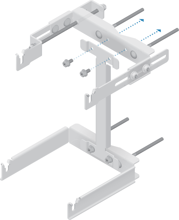
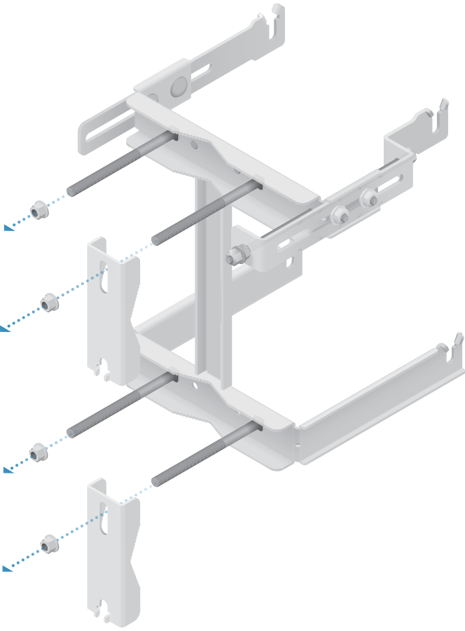
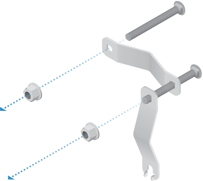
| Note: For SISO mode, use the RF connector (H or V) as determined by your licensing. Keep the other RF connector covered with the included Metal Cap. |
|---|
Pole-Mounting
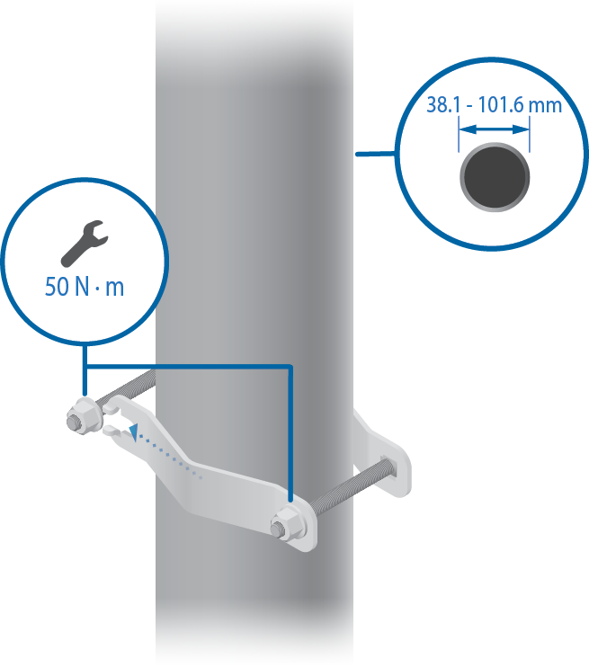
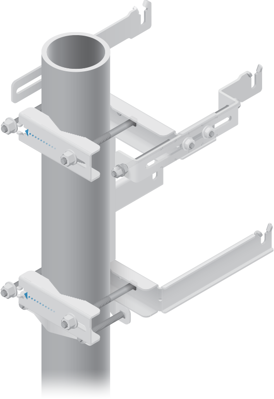
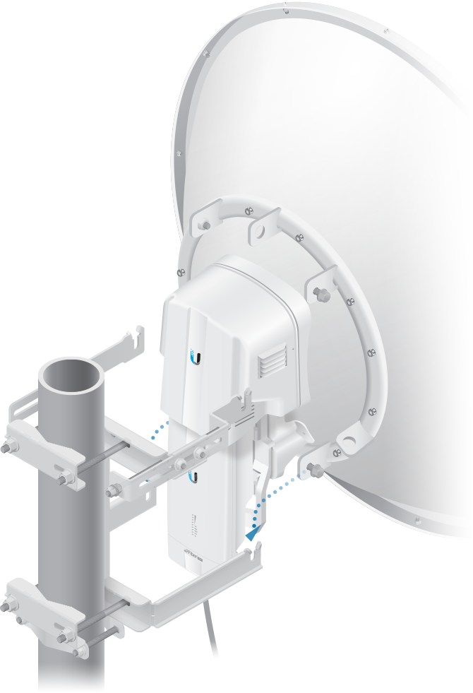
-
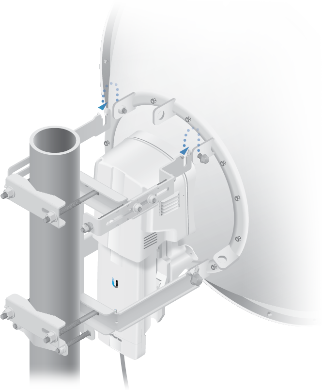
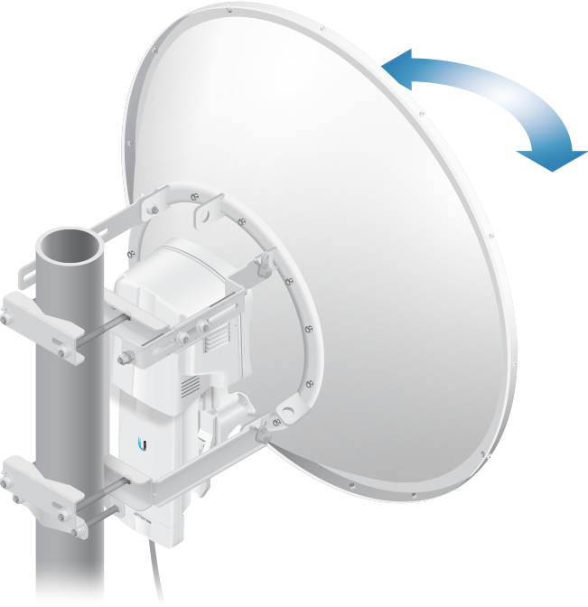
- Secure the free end of the ground wire to a grounded mast, pole, tower, or grounding bar.
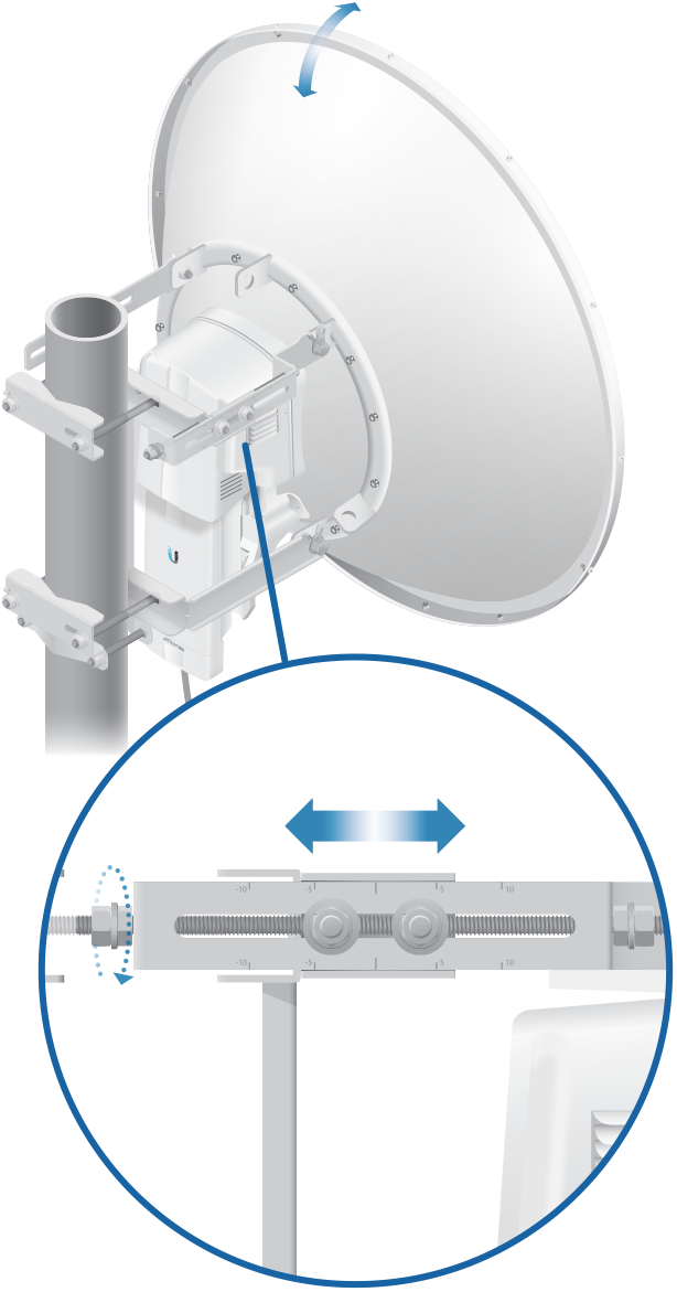
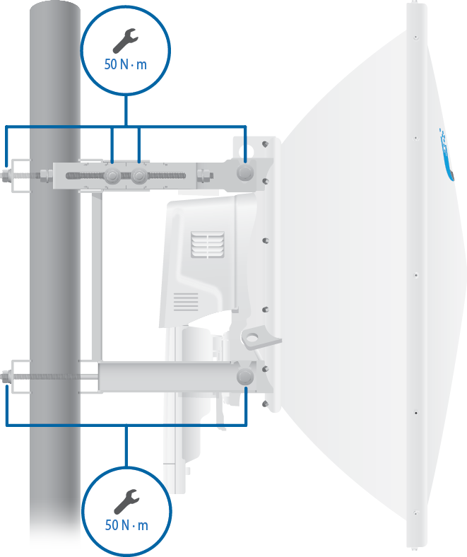
| Note: Hand-tighten the nuts. |
|---|
| WARNING: Failure to properly ground your airFiber radio will void your warranty. |
|---|
| Note: The ground wire should be as short as possible and no longer than one meter in length. |
|---|
Specifications
|
AF-11G35 |
|
|
Dimensions |
811 x 811 x 460 mm (31.9 x 31.9 x 18.1") |
|---|---|
|
Weight |
|
| Mount Not Included | 7.14 kg (15.74 lb) |
| Mount Included | 11.85 kg (26.12 lb) |
|
Frequency |
10.3 to 11.7 GHz |
|
Gain |
35 dBi |
|
HPOL Beamwidth |
2.5° |
|
VPOL Beamwidth |
2.5° |
|
Maximum VSWR |
2:1 |
|
Wind Survivability |
200 km/h (125 mph) |
|
Wind Loading |
1538 N @ 200 km/h |
|
Polarization |
|
| Default | H/V |
| After Rotating OMT | ± 45° |
|
Cross-Pol Isolation |
35 dB |
|
Mounting |
Uses the AF-5 Mounting System |
|
Pattern Regulatory |
ETSI 302 217-4-2, Class 3 and FCC Cat B |
