Package Contents
 |
|---|
| airFiber AF-11 |
 |
|---|
| Zip Ties (Qty. 2) |
 |
|---|
| airFiber Gigabit PoE (50V, 1.2A) |
 |
|---|
| Power Cord |
Antenna Compatibility
The airFiber AF-11 radio is designed for use with the airFiber X antenna model AF-11G35*.
* Check your local/regional regulations for the antenna gain allowed for your application
Installation Requirements
- Clear line of sight between airFiber radios
- Vertical mounting orientation
- Mounting point:
- At least 1 m below the highest point on the structure
- For tower installations, at least 3 m below the top of the tower
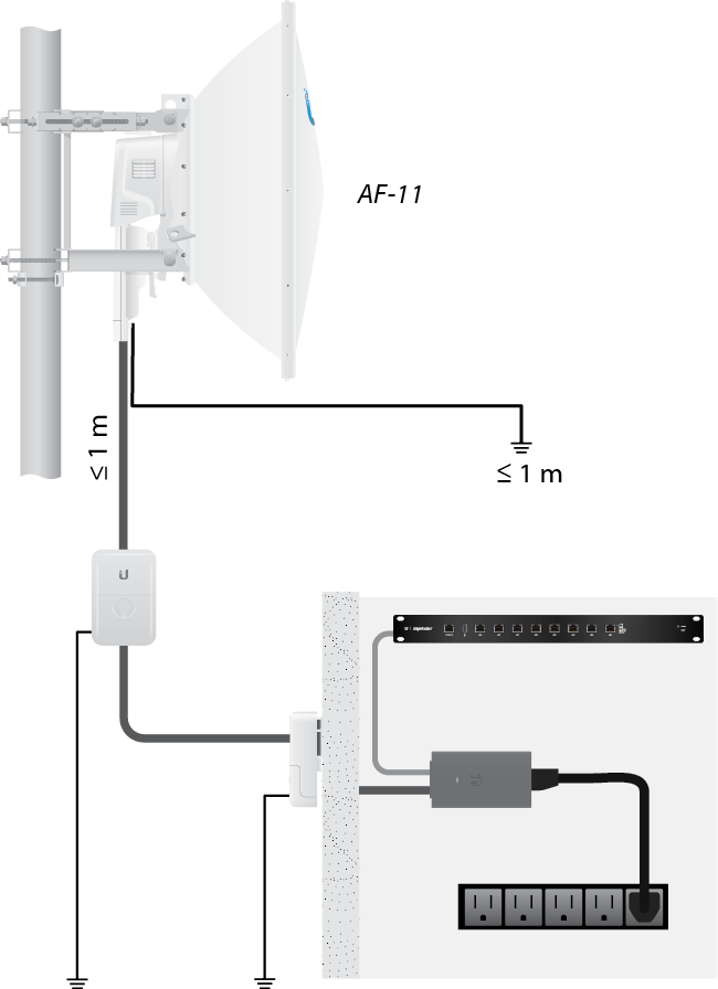
- Ground wires – min. 10 AWG (5 mm2) and max. length: 1 m. As a safety precaution, ground the airFiber radio to grounded masts, poles, towers, or grounding bars.
- (Recommended) 2 Outdoor Gigabit PoE surge protectors
- High-Band Duplexer(s) (model AF-11-DUP-H) or Low-Band Duplexer(s) (model AF-11-DUP-L) are required for proper operation:
- SISO mode: One Duplexer of either band type
- MIMO mode: Two Duplexers of the same band type

Note: Duplexers must be purchased separately. The Duplexer(s) must match the terms of your license (frequency bands and polarities allowed).
- (Optional) If not using PoE: DC power source and 12/30 AWG power cable
- Outdoor, shielded Category 6 (or above) cabling and shielded RJ-45 connectors are required for all wired Ethernet connections.
| WARNING: Failure to properly ground your airFiber radio will void your warranty. |
|---|

| Note: For guidelines about grounding and lightning protection, follow your local electrical regulatory codes. |
|---|
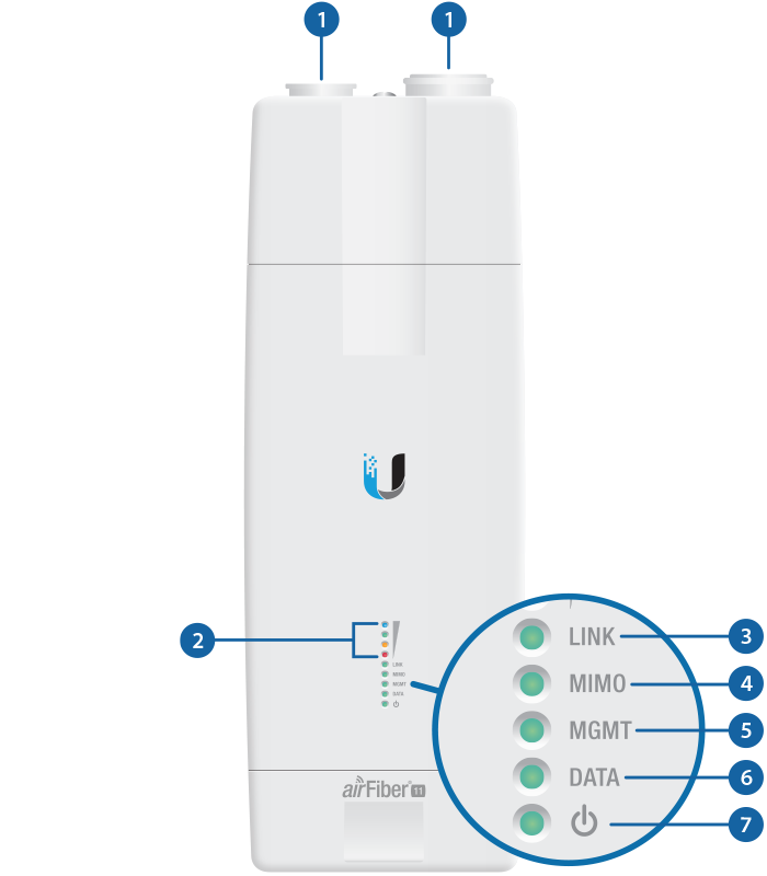
Hardware Overview

 |
 |
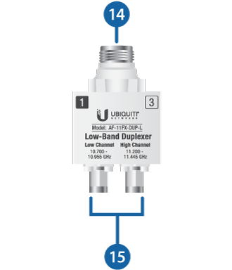
Low-Band Duplexer |
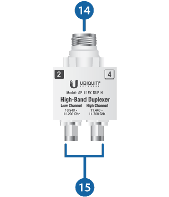
High-Band Duplexer |

Chain 0 / Chain 1 |
|||||||||||||||||||||||||||||||||||||||||||||
|---|---|---|---|---|---|---|---|---|---|---|---|---|---|---|---|---|---|---|---|---|---|---|---|---|---|---|---|---|---|---|---|---|---|---|---|---|---|---|---|---|---|---|---|---|---|
When the Chain 0 or Chain 1 duplexer is installed, its N-type connector is located here, allowing connection to an RF cable (Chain 1 is covered by the removable duplexer cap). |
|||||||||||||||||||||||||||||||||||||||||||||

Signal LEDs |
|||||||||||||||||||||||||||||||||||||||||||||
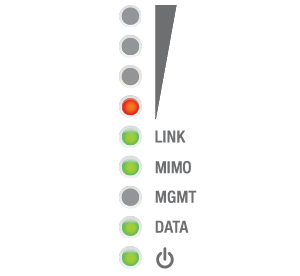
Bootup to airOS When powering on, the Power, MIMO, LINK, and Signal 1-4 LEDs light on. Once the CPU code takes over, the MIMO, LINK, and Signal 1-3 LEDs turn off. Signal 4 LED remains lit to indicate the boot sequence is underway. Initializing airFiber Software When the airFiber application begins to boot under airOS®, the Signal 4 LED goes from solidly on to a 2.5 Hz flash. This continues until the AF‑11FX is fully booted. Signal Level Once fully booted, the Signal 1-4 LEDs act as a bar graph showing how close the AF‑11FX is to ideal aiming. This is auto-scaled based on the link range, the antenna gains, and the configured TX power of the remote AF‑11FX. Each Signal LED has three possible states: On, Flashing, and Off. All Signal LEDs would be solidly on in an ideal link. For example, if the link has a 1 dB loss, the Signal 4 LED will flash; a 2 dB loss and the Signal 4 LED will turn off. The full bar graph LED states are shown below.
|
|||||||||||||||||||||||||||||||||||||||||||||

Link LED |
|||||||||||||||||||||||||||||||||||||||||||||
Off |
RF Off |
||||||||||||||||||||||||||||||||||||||||||||
 |
Syncing |
||||||||||||||||||||||||||||||||||||||||||||
 |
Beaconing |
||||||||||||||||||||||||||||||||||||||||||||
 |
Registering |
||||||||||||||||||||||||||||||||||||||||||||
On |
Operational |
||||||||||||||||||||||||||||||||||||||||||||

MIMO LED |
|||||||||||||||||||||||||||||||||||||||||||||
Off |
Radio Configured in SISO Mode |
||||||||||||||||||||||||||||||||||||||||||||
On |
Radio Configured in MIMO Mode |
||||||||||||||||||||||||||||||||||||||||||||

MGMT LED |
|||||||||||||||||||||||||||||||||||||||||||||
Off |
No Ethernet Link |
||||||||||||||||||||||||||||||||||||||||||||
On |
Ethernet Link Established |
||||||||||||||||||||||||||||||||||||||||||||
Random Flash |
Ethernet Activity |
||||||||||||||||||||||||||||||||||||||||||||

Data LED |
|||||||||||||||||||||||||||||||||||||||||||||
Off |
No Ethernet Link |
||||||||||||||||||||||||||||||||||||||||||||
On |
Ethernet Link Established |
||||||||||||||||||||||||||||||||||||||||||||
Random Flash |
Ethernet Activity |
||||||||||||||||||||||||||||||||||||||||||||

Power LED |
|||||||||||||||||||||||||||||||||||||||||||||
Off |
No Power |
||||||||||||||||||||||||||||||||||||||||||||
On |
Powered On |
||||||||||||||||||||||||||||||||||||||||||||
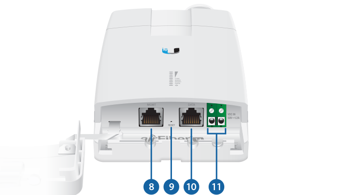
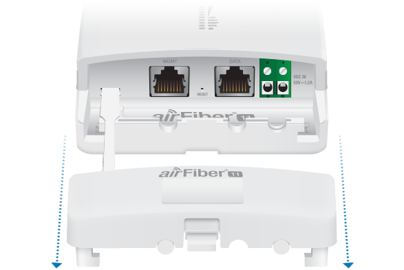
 Management Port |
|||||||||||||||||||||||||||||||||||||||||||||
10/100 Mbps, secured Ethernet port for configuration. In-Band Management is enabled by default in the airFiber Configuration Interface. When In-Band Management is disabled, the MGMT port is the only port that can monitor, configure, and/or update firmware. |
|||||||||||||||||||||||||||||||||||||||||||||
 Reset Button |
|||||||||||||||||||||||||||||||||||||||||||||
To reset to factory defaults, press and hold the Reset button for more than 10 seconds while the device is already powered on. |
|||||||||||||||||||||||||||||||||||||||||||||
 Data Port |
|||||||||||||||||||||||||||||||||||||||||||||
Gigabit PoE port for handling all user traffic and powering the device. |
|||||||||||||||||||||||||||||||||||||||||||||
 VDC IN |
|||||||||||||||||||||||||||||||||||||||||||||
The terminal block can be used to power the AF-11 with +50VDC, 1.2A instead of PoE. |
|||||||||||||||||||||||||||||||||||||||||||||
 TX 0, RX 0 |
|||||||||||||||||||||||||||||||||||||||||||||
The TX and RX SMA ports for the Chain 0 Low-Band Duplexer or High-Band Duplexer (SISO and MIMO modes). |
|||||||||||||||||||||||||||||||||||||||||||||
 RX 1, TX 1 |
|||||||||||||||||||||||||||||||||||||||||||||
The RX and TX SMA ports for the Chain 1 Low-Band Duplexer or High-Band Duplexer (MIMO mode only). In SISO mode, these unused ports are protected by the duplexer cap. |
|||||||||||||||||||||||||||||||||||||||||||||
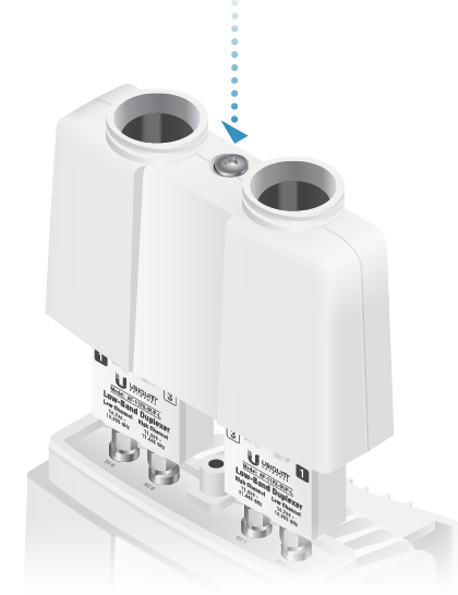
 N Connector |
|||||||||||||||||||||||||||||||||||||||||||||
Female N-type connector into which the antenna cable is plugged. |
|||||||||||||||||||||||||||||||||||||||||||||
 SMA Port |
|||||||||||||||||||||||||||||||||||||||||||||
High-band and low-band channel SMA ports. |
|||||||||||||||||||||||||||||||||||||||||||||


|
|
Note: Duplexers are not included with the AF-11. SISO mode requires one Low-Band Duplexer or one High-Band Duplexer. MIMO mode requires either two Low-Band Duplexers or two High-Band Duplexers. |
|---|
Installation Overview
We recommend that you configure your paired AF-11 radios before site installation. The overview below summarizes the installation procedure, and the subsequent sections provide detailed installation information.
- Install the Duplexer(s) in the AF-11 radio.
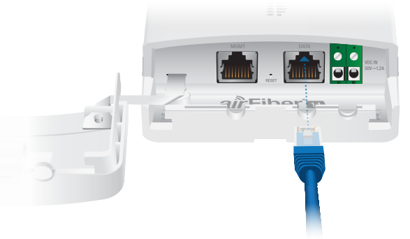
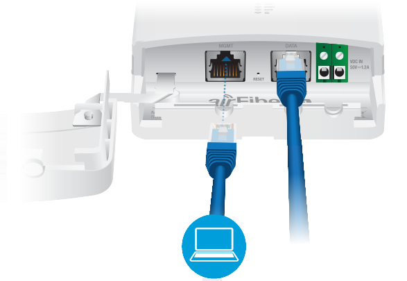
- Connect the airFiber Gigabit PoE adapter to the DATA port, and connect your computer to the MGMT port.
- Configure the AF-11.
- Install a ground wire and mount the AF-11 on the airFiber AF-11G35 antenna (or a compatible antenna).
- At the installation site, install the antenna with the mounted AF-11 radio (see the antenna’s Quick Start Guide for installation instructions).
- Connect the DATA port to your LAN, and connect power (PoE or DC power) to the AF-11.
- Establish and optimize the RF link.
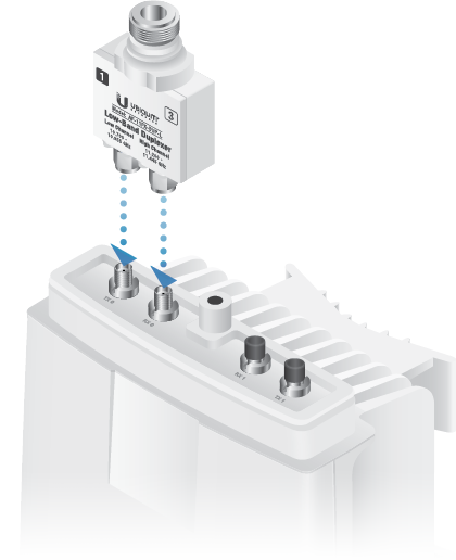
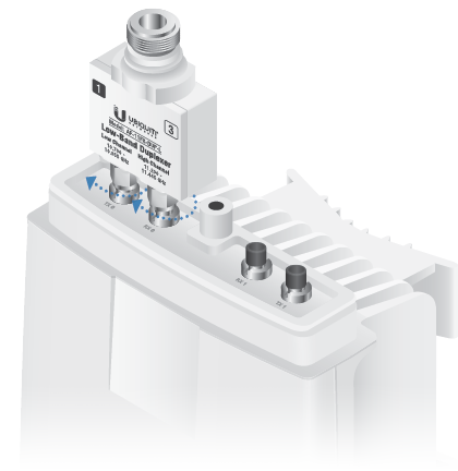
Installing the Duplexers
Installing the Duplexer for SISO Mode
- Repeat steps 1-4 for the radio to be used on the other end of the link, ensuring that the numbers on the second radio’s Duplexer are in the reverse order of the numbers on first radio’s Duplexer.
| Note: Position the low channel and high channel ports to yield the required transmit and receive frequencies. |
|---|
| WARNING: Tighten the collars alternately, a half turn at a time, until both are fully tightened. Failure to do so may result in damage to the Duplexer. |
|---|
| Note: For example, if the numbers on the first radio’s Duplexer are (left to right) 1/3, then the numbers on the second radio’s Duplexer should be 3/1. |
|---|
Installing the Duplexers for MIMO Mode
|
|
Note: MIMO operation requires two licenses, one per polarization and two Duplexers of the same band type. |
|---|
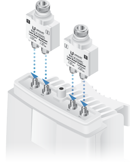
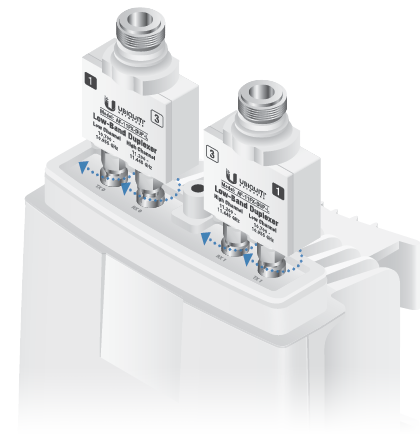
- Repeat steps 1-5 for the other radio to be used in the link, ensuring that the numbers on the second radio’s Duplexers are in the reverse order of the numbers on the first radio’s Duplexers.
| Note: Position the low channel and high channel ports to yield the required transmit and receive frequencies. Also, ensure that the numbers on the right-side Duplexer are in the reverse order of the numbers on the left-side Duplexer. |
|---|
| WARNING: Tighten the collars alternately, a half turn at a time, until both are fully tightened. Failure to do so may result in damage to the Duplexer. |
|---|
|
|
Note: For example, if the numbers on the first radio’s Duplexers are (left to right) 2/4 and 4/2, the numbers on the second radio’s Duplexers should be 4/2 and 2/4. |
|---|
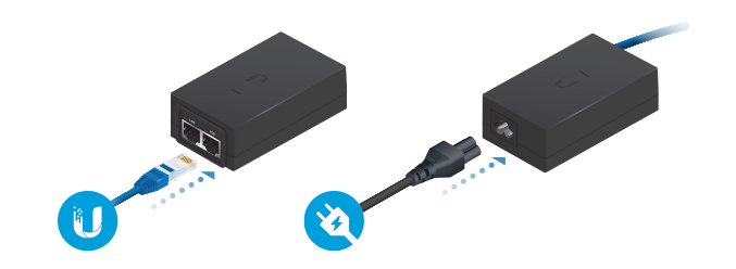
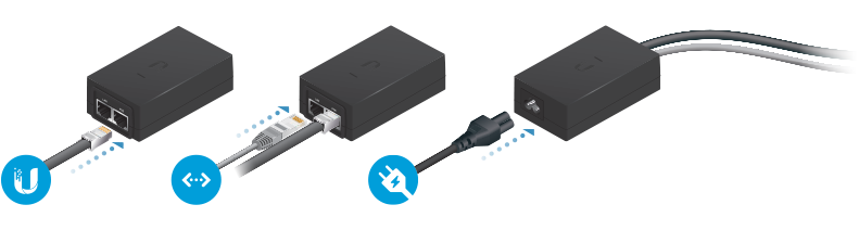
Connecting Power over Ethernet
|
|
WARNING: Use only the included adapter, model POE-50-60W. Failure to do so can damage the unit and void the product warranty. |
|---|
airFiber Configuration
Access the airFiber Configuration Interface and configure the following settings:
- Wireless Mode Configure one AF-11 as the Master and the other as the Slave.
- Frequency Setting The TX Frequency and RX Frequency settings must be the reverse of each other on both the Master and the Slave.
- Configure the Ethernet adapter on your computer with a static IP address on the 192.168.1.x subnet.
- Launch your web browser. Type https://192.168.1.20 in the address field and press enter (PC) or return (Mac).

- The login screen will appear. Enter ubnt in the Username and Password fields. Select your Country and Language. You must agree to the Terms of Use to use the product. Click Login.
- Click Settings, and then click the Wireless tab.
- Configure the Basic Wireless Settings:
- For one AF-11, select Master as the Wireless Mode. For the other AF-11, keep the default, Slave.
- Enter a name in the Link Name field. This should be the same on both the Master and the Slave.
- If needed, change the Channel Bandwidth, Output Power and/or Maximum Modulation Rate settings.
- Configure the TX Frequency and RX Frequency.
- Configure the Wireless Security:
- Select the Key Type, HEX or ASCII.
- For the Key field:
- HEX Enter 16 bytes (eight, 16-bit hexadecimal digits: 0-9, A-F, or a-f). You can omit zeroes and use colons, similar to the IPv6 format.
Note: The airFiber Configuration Interface supports IPv6 formats excluding dotted quad and “::” (double-colon) notation.
- ASCII Enter a combination of alphanumeric characters (0-9, A-Z, or a-z).
- Click Save Changes.
- In-Band Management is enabled by default, so each airFiber radio must have a unique IP Address. (If the airFiber radios use the same IP Address, you may lose access to the airFiber radios via the DATA ports.) Click the Network tab.
- For the Management IP Address option:
- DHCP Keep the default, DHCP, to use DHCP reservation on your router to assign a unique IP Address.
- Static Change the IP Address, Netmask, and other settings to make them compatible with your network.
- Click Save Changes.
- For the Management IP Address option:
- Disconnect the Ethernet cables from the MGMT and DATA ports on the AF-11. Configuration of the AF-11 radio is complete.
Note: One airFiber radio’s TX Frequency is the other radio’s RX Frequency, and vice versa.
Repeat the instructions in the airFiber Configuration section on the other AF-11 radio.
For details on the airFiber Configuration Interface, refer to the airFiber AF-11FX User Guide, available at: ui.com/download/airfiber
Hardware Installation
Install a Ground Wire
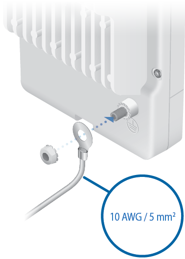
- At the installation site, secure the other end of the ground wire to a grounded mast, pole, tower, or grounding bar.
| WARNING: Failure to properly ground your airFiber radio will void your warranty. |
|---|
| Note: The ground wire should be as short as possible and no longer than one meter in length. |
|---|
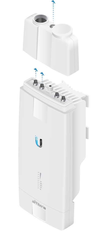
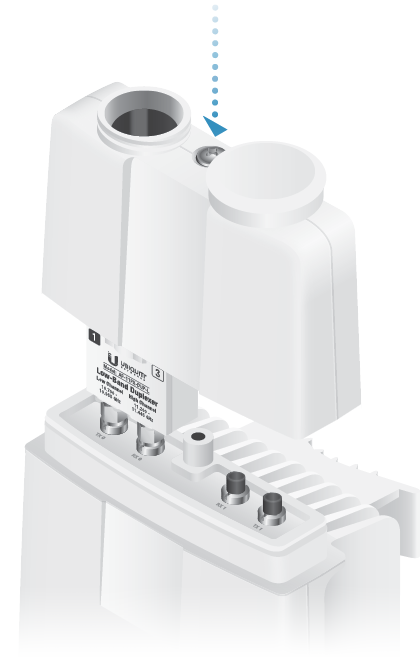
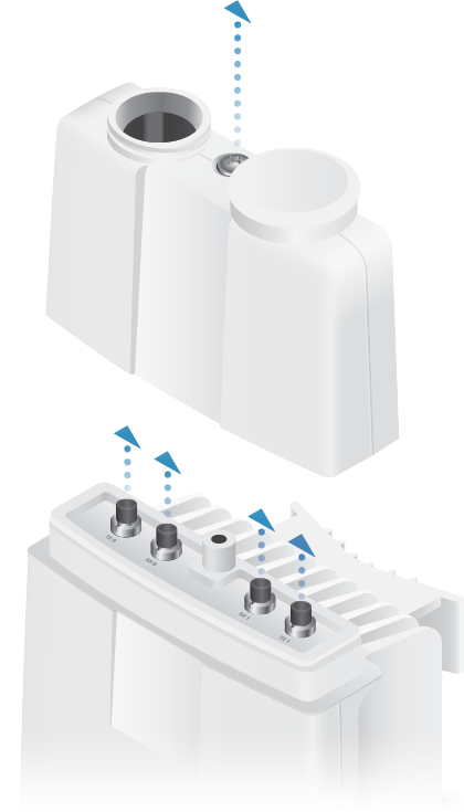
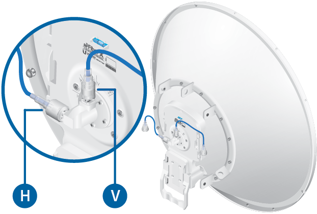
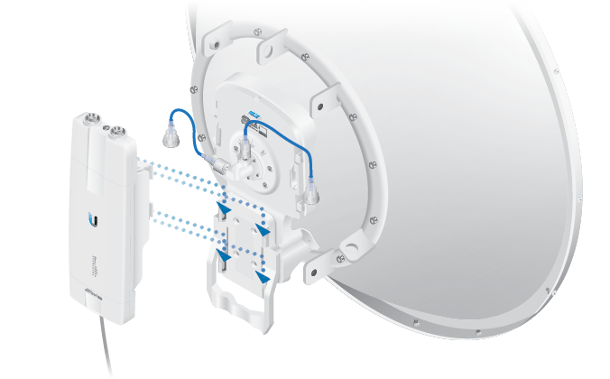
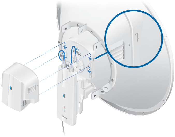
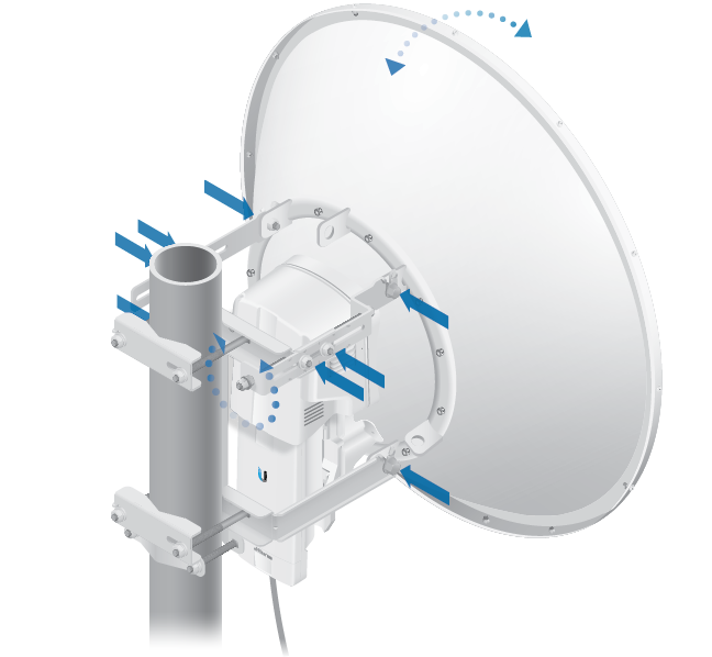
Mount to the airFiber AF-11G35 Antenna
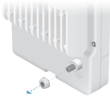
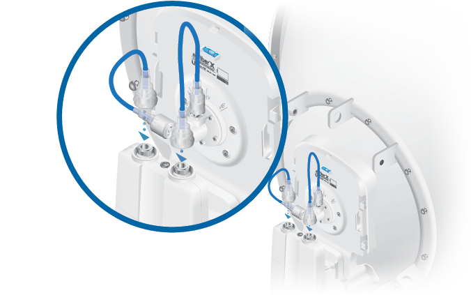
- Attach an RF Cable to an RF connector labeled H or V. Then slide the silicone boot over the RF connector to protect it.
Note: For SISO mode, use the RF connector (H or V) as determined by your licensing. Keep the other RF connector covered with the included Metal Cap.
If using MIMO mode, remove the cap over the second RF connector (V or H) and attach an RF Cable. Then slide the silicone boot over the RF connector to protect it.
-
|
|
Note: Align the dot on the side of the shroud with the arrowhead on the dish antenna. |
|---|
Connecting Data
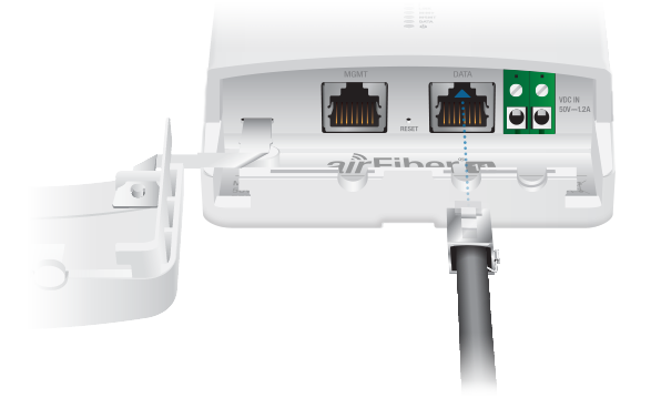
- If you are using DC power, connect the other end of the Ethernet cable to your LAN.
Connecting Power
Follow the instructions for the source of power that you are using: Power over Ethernet or DC Power.
Power Over Ethernet
|
|
WARNING: Use only the included adapter, model POE-50-60W. Failure to do so can damage the unit and void the product warranty. |
|---|
DC Power
- Connect a DC power cable to the Terminal Block. (The +VDC and GND can be connected to either terminal.)
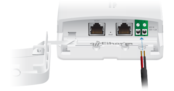
- Connect the other end of the DC power cable to a DC power supply that supplies +50VDC.
- Connect the DC power supply to its source.
| WARNING: Applying a negative voltage such as -48VDC will damage the radio. |
|---|
Surge Protection
For added protection, install two surge suppressors, such as the Ubiquiti Ethernet Surge Protector, model ETH-SP-G2, at the end of each link. Install the first surge protector within one meter of the airFiber DATA port, and install the second surge protector at the ingress point of the location housing the wired network equipment.
Alignment
Tips
- To accurately align the airFiber radios for best performance, you MUST align only one end of the link at a time.
- You may need to use additional hardware to compensate for issues such as the improper orientation of a mounting pole or significant elevation differences between airFiber radios.
Establishing a Link
Adjust the positions of the Master and the Slave to establish a link. The following section features the airFiber X antenna, AF-11G35:
|
|
Note: The Master must be aimed first at the Slave because the Slave does not transmit any RF signal until it detects transmissions from the Master. |
|---|
- Master Visually aim the Master at the Slave. To adjust the Master’s position, adjust the azimuth and the elevation.
Adjust the azimuth:
- Loosen the four flange nuts on the two pole clamps.
- Rotate the antenna to point towards the other end of the link.
- Tighten the four flange nuts on the two pole clamps.
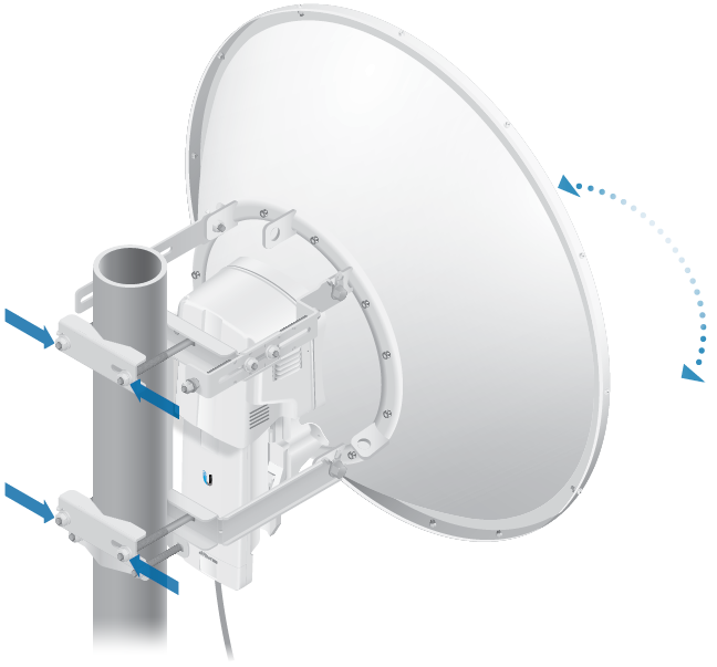
Adjust the elevation angle:
- Loosen the eight hex head bolts to so that the washers can spin freely by hand.
- Tighten or loosen the Elevation Adjustment Bolt to set the desired tilt.
- Tighten the eight hex head bolts.
- Slave Visually aim the Slave at the Master. To adjust the Slave’s position, adjust the azimuth and elevation as described in step 1.
- Check to see if a link is established. Ensure that the LINK LED is solidly lit green and the Signal LEDs of the Slave are displaying signal levels.
- Slave Aim the Slave at the Master to achieve the strongest signal level on the Master.
- Master Aim the Master at the Slave to achieve the strongest signal level on the Slave.
- Repeat steps 4 and 5 until you achieve an optimal link, with all four Signal LEDs solidly lit. This ensures the best possible data rate between the airFiber radios.
- Lock the alignment on both airFiber antennas by tightening all the nuts and bolts.
- Observe the Signal LEDs of each airFiber radio to ensure that the values remain constant while tightening the nuts and bolts. If any LED value changes during the locking process, loosen the nuts and bolts, finalize the alignment of each airFiber antenna again, and retighten the nuts and bolts.
|
|
Note: Do NOT make simultaneous adjustments on the Masterand Slave. |
|---|
| Note: Refer to the Signal LEDs section for details on the signal values. |
|---|
| Note: Maximum signal strength can best be achieved by iteratively sweeping through both azimuth and elevation. |
|---|
For detailed information on setting up an airFiber link, see the airFiber AF-11FX User Guide available at: ui.com/download/airfiber
Installer Compliance Responsibility
Devices must be professionally installed and it is the professional installer’s responsibility to make sure the device is operated within local country regulatory requirements.
The Output Power, Antenna Gain, Cable Loss*, TX Frequency and RX Frequency fields are provided to the professional installer to assist in meeting regulatory requirements.
* Cable Loss includes loss due to the Duplexer(s).
Specifications
|
airFiber AF-11 |
|
|
Dimensions |
327 x 112 x 86 mm (12.87 x 4.41 x 3.39") |
|---|---|
|
Weight |
2.26 kg (5.0 lb) |
|
RF Connectors |
(4) SMA Weatherproof, Two per Chain: |
|
Power Supply |
50V, 1.2A PoE Gigabit Adapter (Included) |
|
Power Method |
Passive Power over Ethernet, DC Power Block |
|
Supported Voltage Range |
38-56VDC |
|
Certifications |
FCC Part 101, ETSI EN 302 217 |
|
Mounting |
AF-11G35 Mount Compatible |
|
Operating Temperature |
-40 to 55° C (-40 to 131° F) |
|
Networking Interface |
|
| Data | (1) 10/100/1000 Ethernet Port |
| Management | (1) 10/100 Ethernet Port |
|
System |
|
|
Processor |
INVICTUS™ 2 IC |
|---|---|
|
Maximum Throughput |
1.2+ Gbps |
|
Encryption |
128-bit AES |
|
OS |
airOS F |
|
Wireless Modes |
SISO/MIMO |
|
Radio |
|
|
Operating Frequency |
10.7-11.7 GHz |
|---|---|
|
Max. Conducted TX Power |
30 dBm |
|
Frequency Accuracy |
± 1 ppm |
|
Channel Bandwidth |
3.5/5/7/10/14/20/28/30/40/50/56 MHz Selectable2 Programmable Uplink and Downlink Duty Cycles |
1 For region-specific details, refer to the Compliance chapter
of the airFiber AF-11FX User Guide at ui.com/download/airfiber
2 Channel widths may vary according to country/region regulations.