NETSHe for OpenWRT
Web interface and custom firmware
User Manual
Stanislav Korsakov
(с) 2009
Yaroslavl
Content
MAIN FEATURES OF NETSHe
GETTING STARTED
Firmware Flashing
USING WEB INTERFACE
Getting Started
Setup Wizard
General Web Interface Layout
Start Page
System Information
Recommended system settings sequence
System
Network
Routes
Services
Utilities
Diagnostics
How to build OpenWRT based firmware with NETSHe for Ubiquity RouterStation
Credits
The system uses Yahoo User Interface library (http://yui.yahoo.com). The library is licensed under BSD license.
The system uses PHPMailer - PHP email transport class. Author Brent R. Matzelle.
The code is licensed under LGPL license.
The system uses a code from phpsysinfo project (http://sourceforge.net/projects/phpsysinfo). The code is licensed under GPL v2 license.
The system uses some code from m0n0wall project. The code is licensed under BSD license.
The system uses some code from pfsense and from Scott Ulrich. The code is licensed under BSD license.
Some icons and images are part of Tango (Authors - Ulisse Perusin <uli.peru@gmail.com>, Steven Garrity <sgarrity@silverorange.com>, Lapo Calamandrei <calamandrei@gmail.com>, Ryan Collier <rcollier@novell.com>, Rodney Dawes <dobey@novell.com>, Andreas Nilsson <nisses.mail@home.se>, Tuomas Kuosmanen <tigert@tigert.com>, Garrett LeSage <garrett@novell.com>, Jakub Steiner <jimmac@novell.com>).
Icon set is licensed under Creative
Commons 2.5 license). Nuvola icon set is licensed under LGPL v2.1
license. Author David Vignoni (david@icon-king.com).
Some other graphics has its authors and is licensed under GPL v.2 license.
Other code and graphics were developed by Stanislav Korsakov and are licensed under GPL v.2 license.
In the event you discover any breach of copyright, please contact Stanislav Korsakov <sta@stasoft.net>.
This software is a custom image of OpenWRT (kamikaze) with Linux 2.6 kernel.
Therefore, you can use the full set of software available for this
version of OpenWRT and, with relevant patches, for all Linux based
operating systems.
The system was developed in sh, php
and javascript. The basic distinctive feature of NETSHe is that is has
its own system configuration storage, pre-installed software and its
own initialization system (start-up scripts).
All system settings and used software settings are stored in one
configuration XML-file. This solution ensures an integrated space of
system settings, maximum monitoring of settings and their automatic
modification for all applications from single point.
For instance, if some network interface is deleted through the web
interface, then this network interface will be automatically deleted
from all applications, which used it. Any modification of radius-server
settings will lead to automatic modification of these settings for all
applications using radius-server.
It should be noted, however, that this approach is totally incompatible
with UCI configuration system, which is standard for OpenWRT Kamikaze.
NETSHe start-up scripts, based on the data from XML-file, directly
configure the respective system services or create configuration files
for specific applications (in their “native” format) in a temporary
directory immediately before starting an application.
How NETSHe gains control over the system?
During the first system boot (and after new firmware flashing) a
special script is the first to gain control over the system. This
script replaces kamikaze start-up scripts and configuration files (UCI
files) with NETSHe files and re-boots the device.
After the second boot the device is initialized in accordance with the device default settings.
NETSHe configuration file is named .main.conf and is located in /etc/.ssxapp directory.
Configuration files for some applications (e. g. for bgp router) are created by the system in the /tmp/etc directory.
Besides, NETSHe creates and uses some files in /tmp directory.
NETSHe files are located in /opt/rb directory.
MAIN FEATURES OF NETSHe
- Network interface management (including point-to-point and wireless);
- VLAN's and aliases;
- Advanced routing (static, multipath, rule-based, RIP, OSPF, BGP);
- Zone based firewall;
- Bridges with brouter and filtering capability;
- Interface bonding;
- Quality of Service, bandwidth management, traffic shaping, rate control and traffic prioritization;
- L7 based (application patterns based) IP-traffic filtering and marking;
- Extended management of wireless interfaces; Access Point, Ad-Hoc,
Client and Repeater mode with (or without) variable WEP encryption
modes, WPA-PSK, WPA2-PSK, WPA-EAP, WPA2-EAP, 802.11X authorization and
key management;
- Access concentrator for variable VPN's (PPTP, L2TP and OpenVPN);
- IPSEC support for L2TP VPN solution;
- PPPoE access concentrator;
- Hot-spot controller with external UAM-authorization; walled garden and bandwidth management;
- Authorization and accounting through external radius-server;
- Built-in IP-address assignment or assignment through external radius-server;
- DHCP server with flexible rules; dynamic IP-address assignment;
static IP-address assignment; configurable black-list mode for DHCP
requests from specified MAC's;
- DHCP relay;
- Network time synchronization server and client. Server integration with DHCP server.
- Built-in HTTP proxy with ability to use upstream proxy;
- Full software management; support of external software repositories; software installation and deletion;
- User management; two levels of user access: full and read-only;
- External storage management; SWAP control;
- System monitoring; chart graphing in a near real-time mode;
- System monitoring through SNMP v2 protocol;
- Configurable system backup; backup images can be moved to external devices and/or network shares;
- Files and folders restoration;
- Backup and restoration of configurations;
- Firmware flashing;
- Traffic capture and analysis;
- System halt and reboot;
- Some helpful utilities.
GETTING STARTED
Firmware Flashing
To flash new firmware into the RouterStation you would require a PC with tftp-client.
Example:
OS Linux with atftp.
Power on RouterStation with pressed service button. The device goes in
RedBoot bootloader mode, assigns 192.168.1.20 with network mask
255.255.255.0 to eth0 (POE port) and waits for tftp connection to
receive new firmware image.
Make sure you PC is connected to the same network as the device. Assign
an IP-address from the same network to the network interface of your PC
(e. g. ifconfig eth0:1 inet 192.168.1.1 netmask 255.255.255.0 up) and launch atftp.
From atftp-shell type in:
verbose
trace
connect 192.168.1.20
put Path_to_firmware_file_image/Firmware_file_name
Monitor firmware flashing process, which takes 3 to 5 minutes. Do not
power of the device! In the event of any unexpected power cut-off
during firmware flashing, start the whole process again from the
beginning.
Firmware flashing ends up with automatic device re-boot. Wait for the
second automatic device reboot, which will enable NETSHe to gain
control over the system.
If firmware flashing is performed successfully, the device becomes
accessible at 192.168.1.20. SSH-access at port 22, web interface at
port 80.
After new firmware flashing the system has only one account with login “root” and password “ubnt”.
USING WEB INTERFACE
Getting Started
Launch browser and visit http://192.168.1.20
It should be noted, that execution of java-scripts and cookies are to be enabled in your browser.
After you typed in the IP-address of the device and pressed “Enter”
key, you get to the page, which checks settings of your browser. If
execution of java-scripts is enabled in your browser, you will be
automatically redirected to the login page of the web interface.
Otherwise, you cannot move any further.
Please check your browser settings and unable execution of java-scripts, if automatic redirection failed.
As soon as you get to the login page, the web interface will try to
detect language settings of your browser and offer the login page in
your native language (provided the system has been translated in your
language). Otherwise, the login page will be in English. You can
choose, however, from the list of available languages.
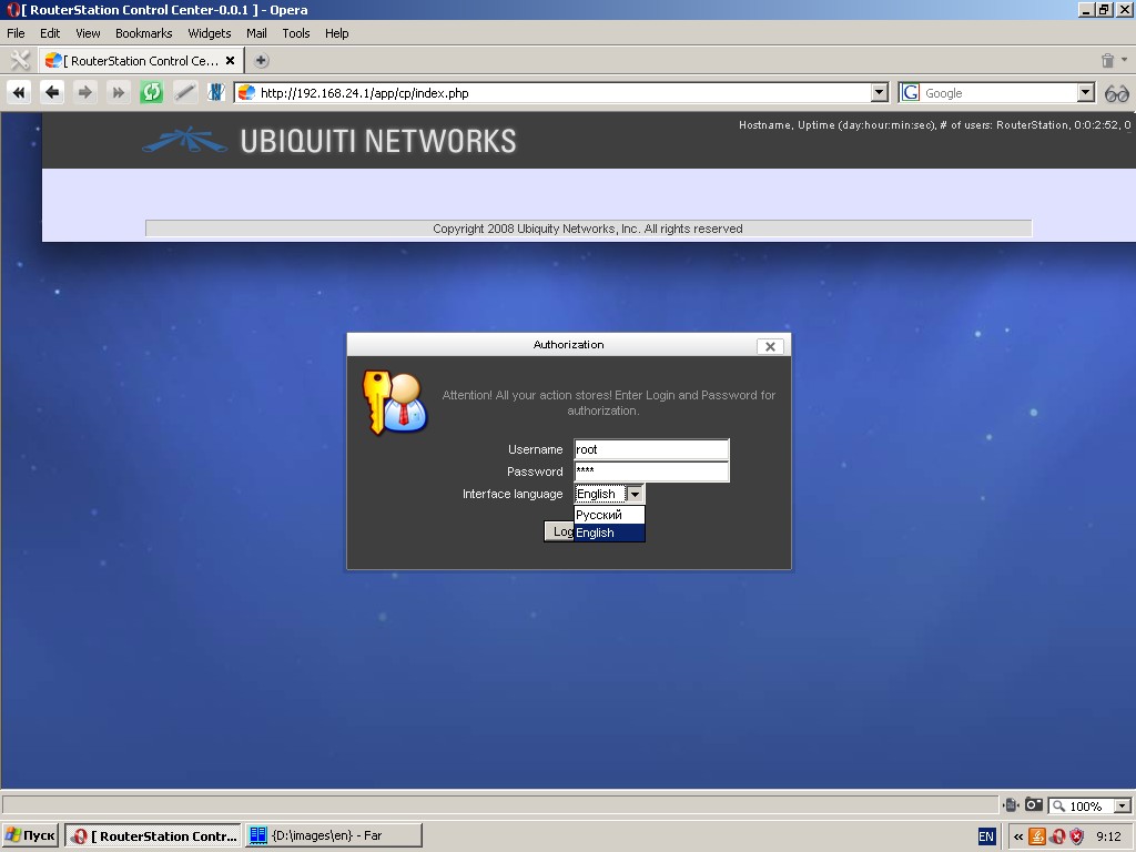
Type in login “root” and password “ubnt”, click “Log in” button.
If you still stick to this page, check if cookies are enabled in your
browser. If your login and password are correct, you get to the setup
wizard.
Setup Wizard
Setup Wizard are several pages, which appear consecutively and enable
you to set up the most important features of your device, such as
IP-addresses of two network interfaces, hostname, time and time zone
and new password for the user “root”.
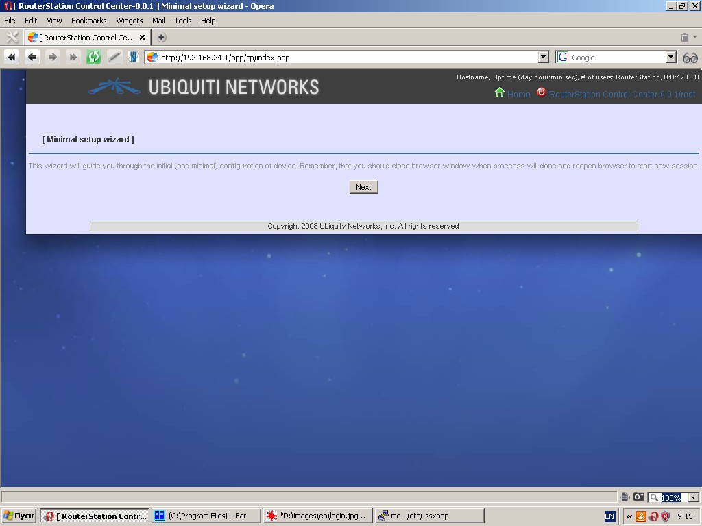
Please remember, that if you change the IP-address or netmask of eth0,
this will drop all current connections. You will have to exit from your
browser and log in at the new IP-address.
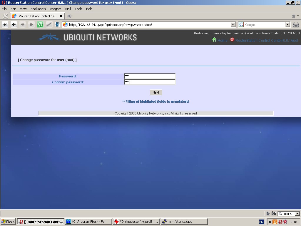
Please change the initial password for user “root” due to security reasons. Please use complex password for user “root”.
If you are not going to change the current device settings, simply click “Next”.
When you finish with setup wizard, exit from your browser.
General Web Interface Layout
Manufacturer’s logo is located in the top of the page. By clicking on the logo you are redirected to the corporate web site of UBIQUITY NETWORKS. Besides, you can find there the following information: hostname, uptime, home button and logout button.
Below is the main dropdown menu, which separates the work area of the
page (data input/output area) from the top part of the page. All
functions of the system are grouped in the main menu.
A toolbar can appear under the main menu with shortcuts to various
specific functions (e. g. “New”, “Create backup”, “Find”, etc.).
Do not forget to click “Save” button after modification of any settings.
If you tick off the “Restart service(s) after saving” field, the
modified settings will be saved and the relevant service(s) will be
restarted after clicking the “Save” button.
Web interface uses standard icons to identify similar tasks. Thus,  icon is used to identify such actions as “Add new record/property”,
  identifies such actions as removal/termination of service/application,
  identifies editing,
  identifies service/application start. An icon with two reciprocal arrows
  identifies restart/update.
Start Page
Start page has icons and subscripts with links to the most commonly
used functions of the system. By clicking the icon you get to the
settings page of the relevant function.
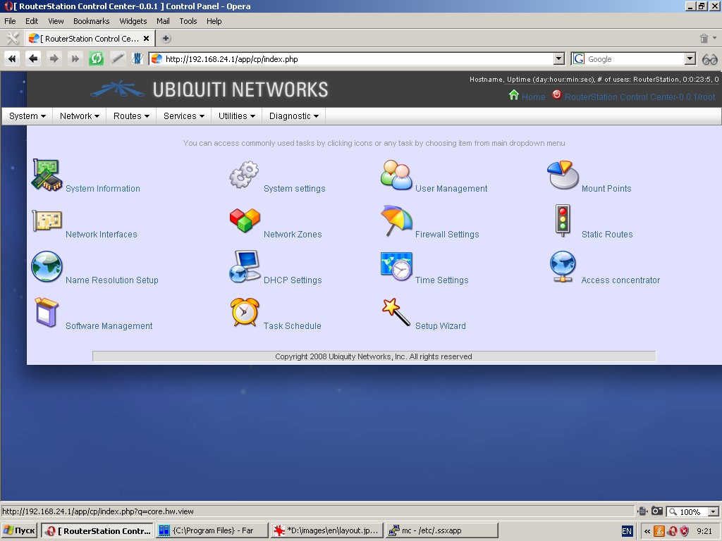
Please note that all these and many other functions of the system are accessible from the main menu.
System Information
During development of the system we were aiming at provision of a
modern and smart tool, which would most efficiently and comfortably
output the system data and the events taking place in the system.
Thus, the following system information is displayed graphically in near
to real-time mode: CPU usage, RAM usage, SWAP usage, OS kernel and
distributive, CPU information, CPU bogomips, USB drivers and
controllers, etc.
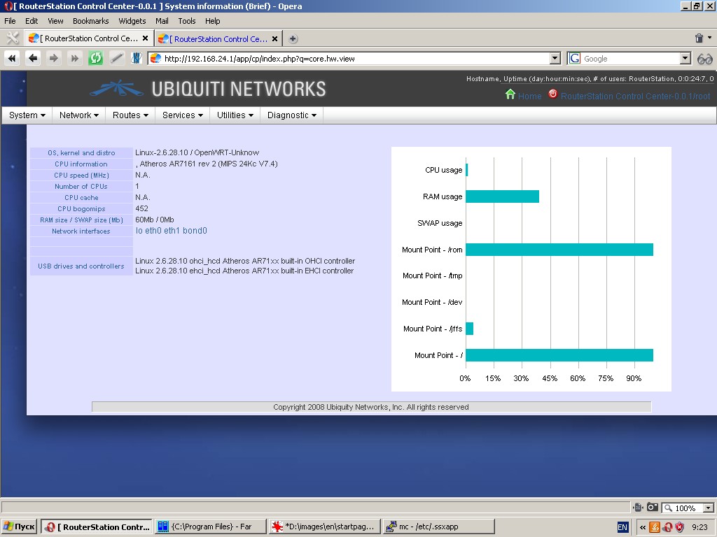
To view the chart you will need Flash Player 10 and above installed in your browser.
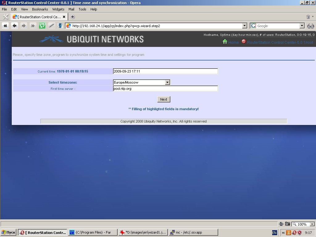
Recommended system setting sequence:
- Change password of user “root”
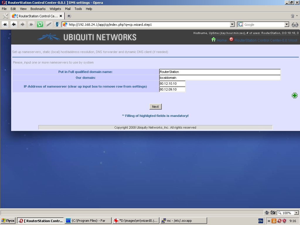
- Specify hostname
- Specify your domain (use localdomain if you are not sure)
- Specify one or more IP-addresses of nameservers
- Type in current date and time
- Select your time zone
- Specify one or more upstream time servers (these settings are
made either by means of Setup Wizard or via the menu items “System-Base
settings”, “Services-Time settings and synchronization”,
“Services-Domain name resolution”.
- Set up network interface eth0
- Set up network interface eth1 (either by means of Setup Wizard or via the menu item “Network-Interfaces”)
- Set up system log (via the menu item “System-Base settings”)
- If necessary, add new users to the system. It should be noted, that any user with shell other than empty shell, /bin/false and /bin/nologin will have full rights to access and control the system via the web interface. User with empty shell, /bin/false or /bin/nologin
will have access to web interface in “read only” mode. Some settings
will not be accessible for such user even in read only mode. (If
necessary, this is performed via the menu item “System-Users”)
- Set up external radius-server. (If necessary, this is performed via the menu item “System-Base settings”)
- Set up external upstream http-proxy (If necessary, this is performed via the menu item “System-Base settings”)
- Set up all optional interfaces (VLAN; aliases; dynamic, i. e.
PPP; wireless. This is performed via the menu item “Network-Interfaces”)
- Create and set up bridges (If necessary, this is performed via the menu item “Network-Bridges”)
- Create and set up interface bonding (If necessary, this is performed via the menu item “Network-Bonding”)
- Group interfaces into zones (at least two zones must be
specified, e. g. Lan and Wan). This is performed via the menu item
“Network-Zones”
- Set up firewall (This is performed via the menu item “Network-Firewall”)
- Set up bridge filtering (If necessary and if the bridge is
available, this is performed via the menu item “Network-Bridge
filtering”)
- Set up static routing. (This is performed via the menu item “Routes-Static”)
- Set up other types of routing. (This is performed via the menu item “Routes”)
- If necessary, mount external storage devices and network shares. (This is performed via the menu item “System-Mount points”)
- If necessary, set up packages repository and install required
software not included in the basic delivery package (This is performed
via the menu item “System-Software”)
- If necessary, set up traffic prioritization and quality of
service assurance system. (This is performed via the menu item
“Network-Bandwidth management and traffic prioritization”)
- Set up required services and additional software.
System
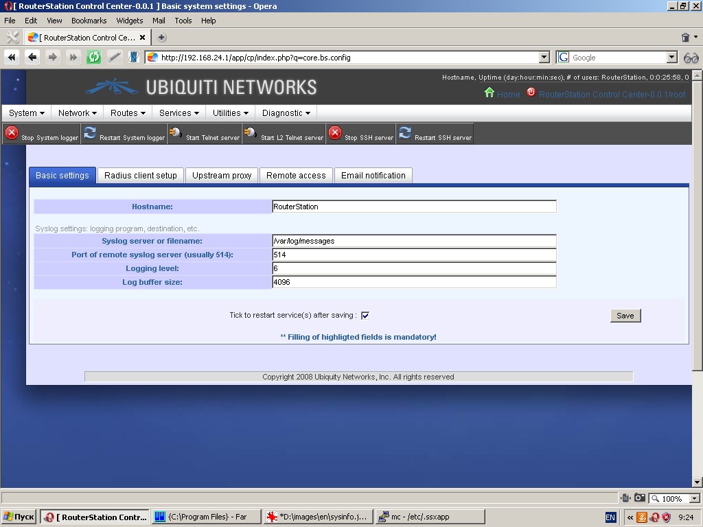
Basic system settings
‘Basic settings’ tab contains fields for typing in hostname, filename
or syslog server (remote syslog server in case of external computer),
port (in case of external computer), logging level and log buffer size,
where new records will clean out old ones in the event of overflow
(cyclic recording).
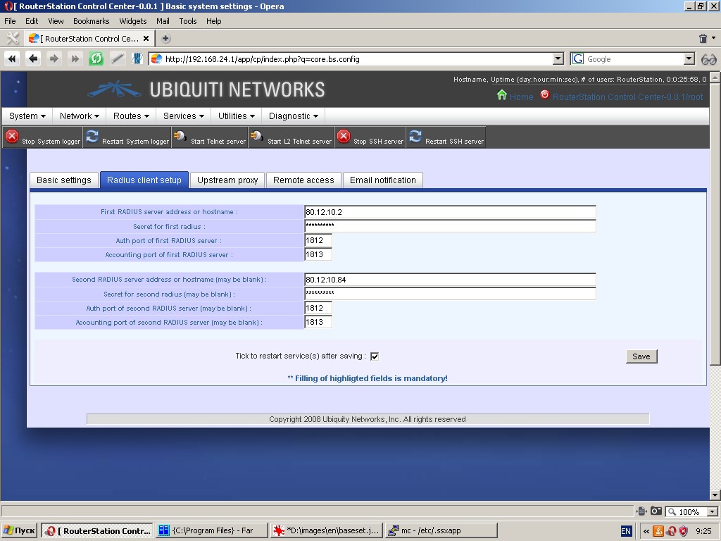
‘Radius client setup’ tab allows to specify up to two radius-servers
(primary and redundant), which can be used by the system for client
authorization and accounting (e. g. during PPTP/PPPoE/L2TP connections
and hot spot controller operation). Radius-servers are identified by
hostname or IP-address, secret phrase and authorization and accounting
ports.
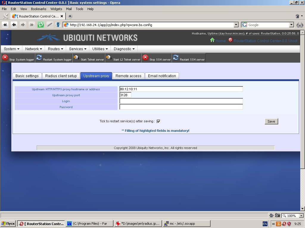
‘Upstream proxy’ tab allows to specify an http-proxy to be used for
redirection of all http-requests from the in-built proxy. This proxy
will also be used as proxy for packages manager and dynamic domain name
resolution client.
To use this function, type in upstream HTTP/HTTPS proxy hostname or
IP-address, upstream proxy port, where the requests are received, login
and password for authorization (if necessary).
‘Remote access’ tab allows to control type and possibilities of remote access to the device.
Remote access to the device can be performed as follows:
- via web interface,
- via telnet,
- via SSH protocol,
- via L2 telnet.
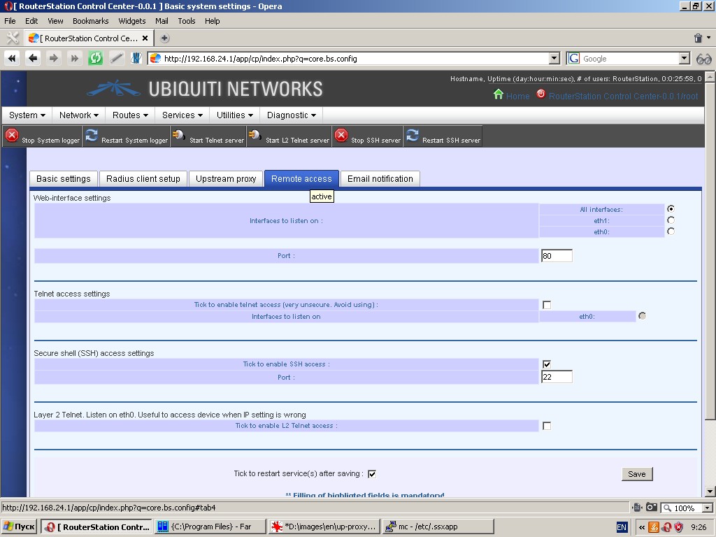
Both types of telnet are disabled by default. Only web interface at
port 80 and SSH access at port 22 for all device interfaces are enabled.
Please remember that telnet access is extremely vulnerable (password is
not requested) and this vulnerability will not be any smaller by trying
to limit telnet by any specific interface. Therefore, we recommend not
to use telnet access at all.
L2 telnet access is available only with eth0 interface and its value is rather theoretical. We don’t recommend to use it either.
SSH access cannot be limited by some specific interface or group of
interfaces, but it can be assigned to a port other than port 22
(standard port), which we urgently recommend to do for your operational
device.
Web interface can be accessible at all device interfaces (by default)
and it can also be assigned to a specific interface. Besides, a port
other than 80 (standard port) can be assigned to the web interface. We
urgently recommend to enable web interface for your operational device
with minimum set of network interfaces and to assign it to a port other
then port 80.
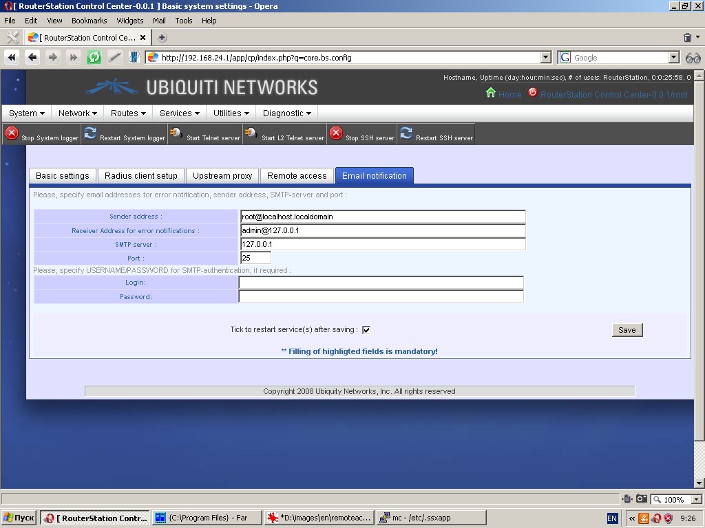
‘Email notification’ tab allows to set up sending of email
notifications by the system (IP-address and port of SMTP server; user
login and password, if necessary; sender and receiver address).
Buttons in the toolbar offer tools for starting, stopping and
restarting of relevant services (web interface, telnet server, etc.)
Users
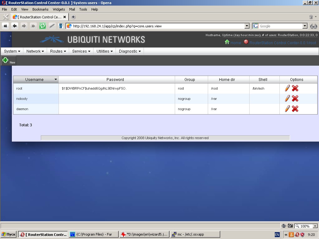
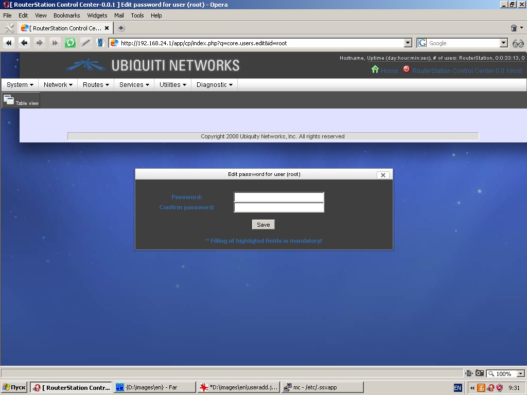
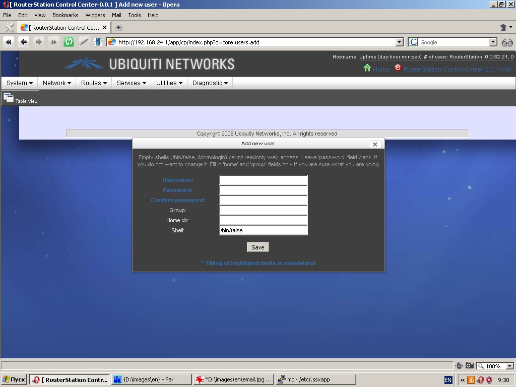
This menu item is a list of system users, where you can add, delete users and edit some user options.
Please remember, that deletion of the user “root” will make the system inoperable. Addition of a user with empty shell, /bin/false or /bin/nologin will create a system user with “read only” access to the web interface.
Icons in the toolbar and the list of users are used for adding a new
user, editing options of existing users and deleting a user.
Editing dialogue contains fields for new password entry and confirmation.
New user entry dialogue also contains fields for username, group, home directory and shell.
Mount points
This menu item tabularizes a list of mounted partitions with
identification of their mount points, filesystem type as well as their
total, used and available capacity. Here you can unmount a partition
(with utmost care).
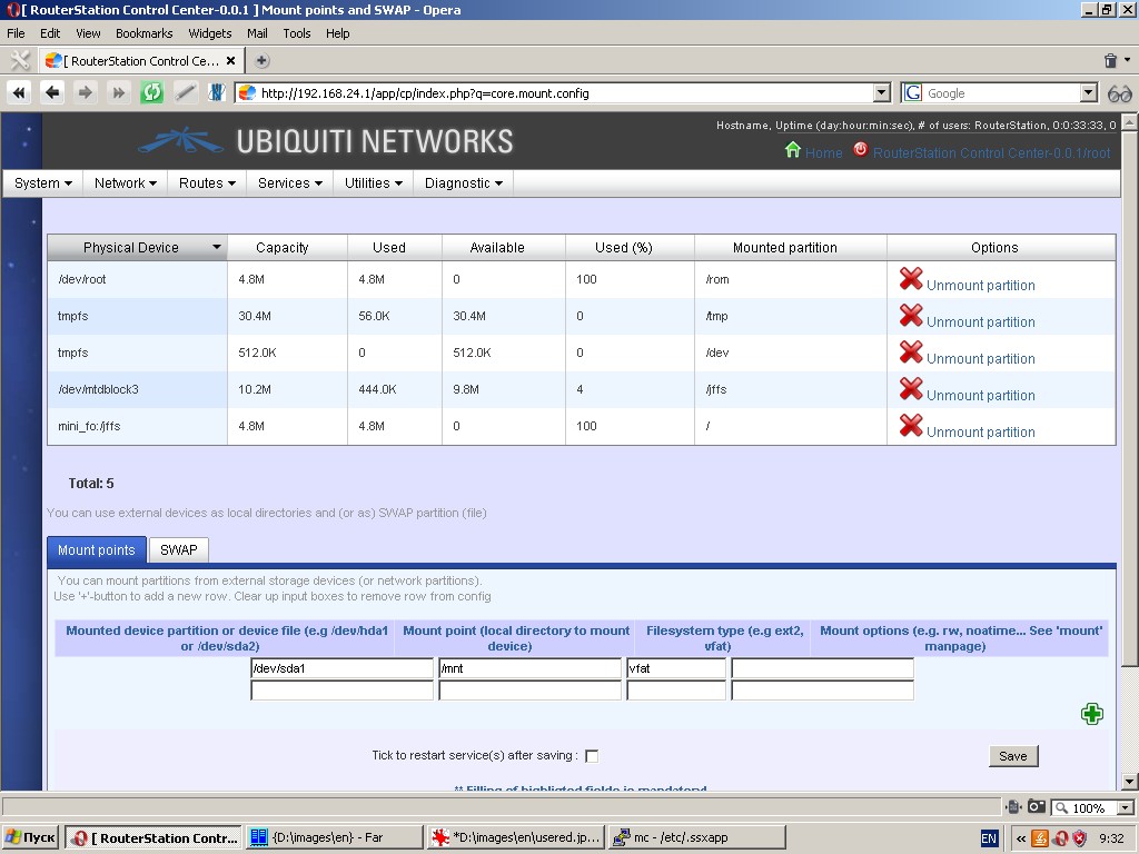
By using the ‘Mount points’ tab you can specify any number of
partitions from external storage devices or network shares to be
mounted to the filesystem of the device.
The following parameters are to be specified: mounted device partition
or device file, local directory to mount device, filesystem type of the
mounted device partition and additional options for mount command.
By using the ‘SWAP’ tab you can specify pre-created swap partitions
(formatted as swap partitions) and files on external devices to
increase RAM (to be used as swap partitions).
Software
Demonstrates in list-form installed software packages with package name
and version. You can remove installed software packages by using a
delete option.
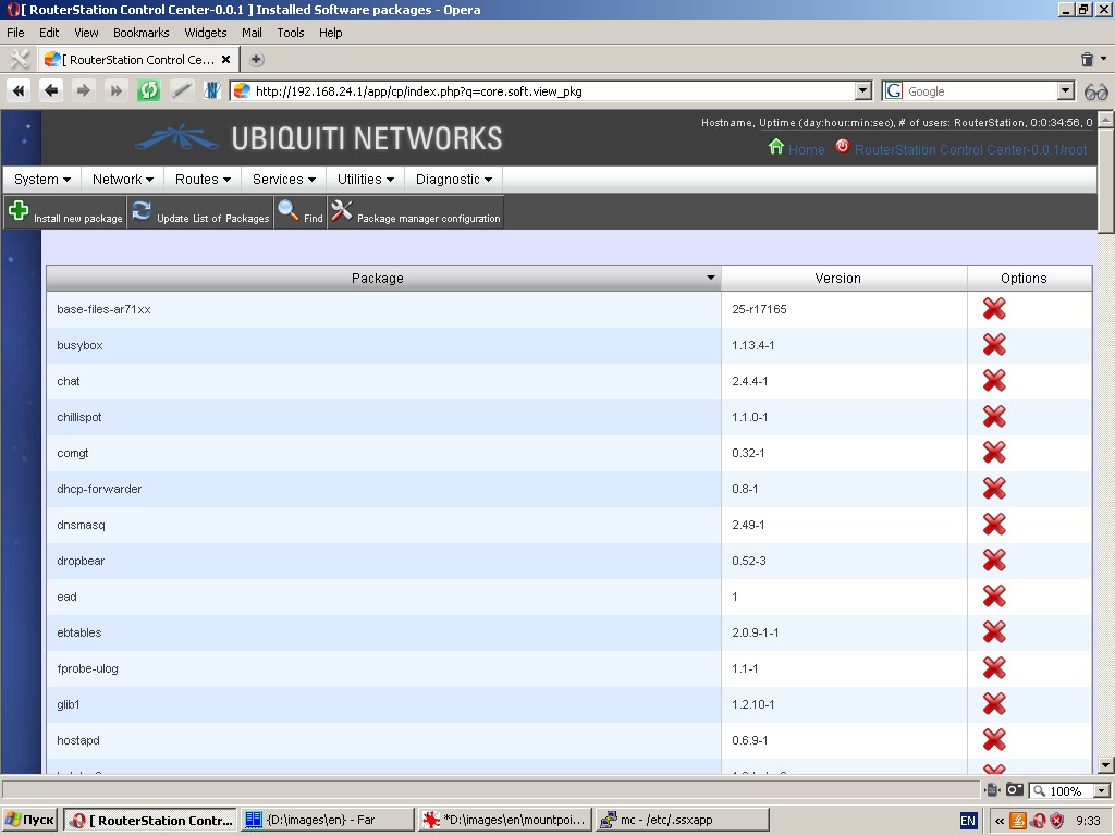
By clicking “Package manager configuration” button in the toolbox you get access to the package manager setup dialogue.
To set up package manager you need to specify one or more repositories
(sources of software packages), as normally required for a relevant
operating system, and tick a box, if necessary, to use upstream proxy.
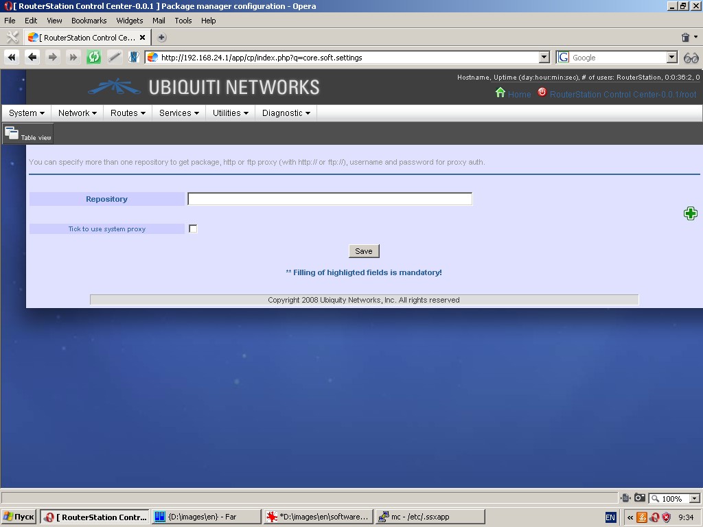
After any modification of the list of repositories you should update
the list packages by clicking the “Update list of packages” button in
the toolbar.
After completion of these steps you can install any software available in the mounted repositories.
Schedule
This page is a job scheduler. Syntax and fields are the same as in ‘cron’ in Linux. It should be noted, that any scheduled jobs will be executed from user “root”.
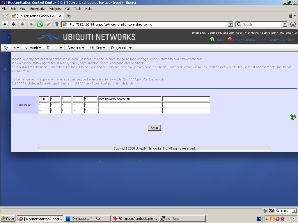
Note: The system includes several jobs into the schedule by default (for instance, network time synchronization client).
Network
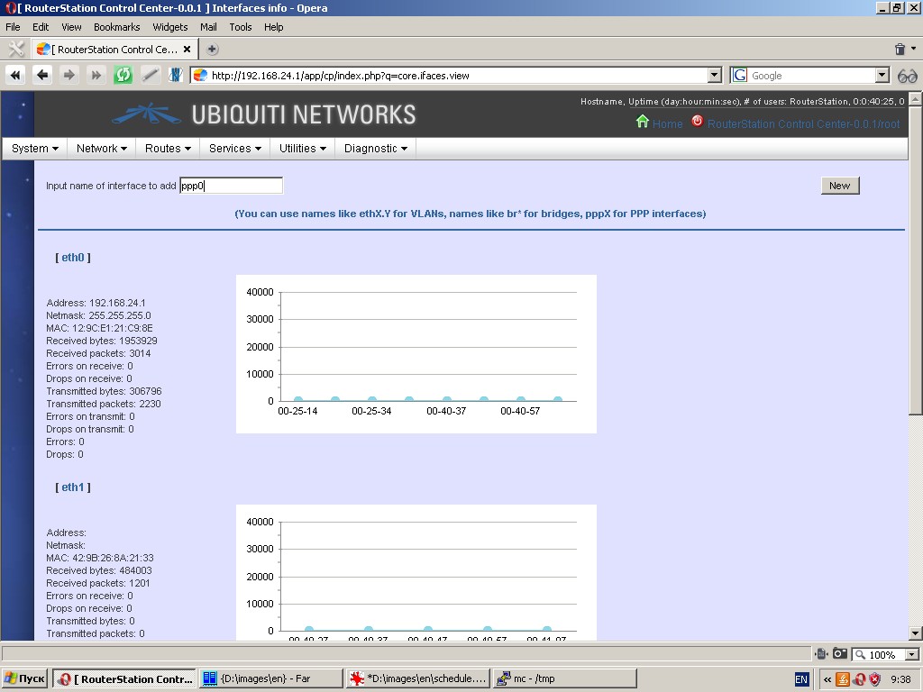
Interfaces
This page displays information (IP-address, netmask, number of sent and
received packets, etc.) about all interfaces existing in the system.
You can specify new interfaces, including virtual ones (using names
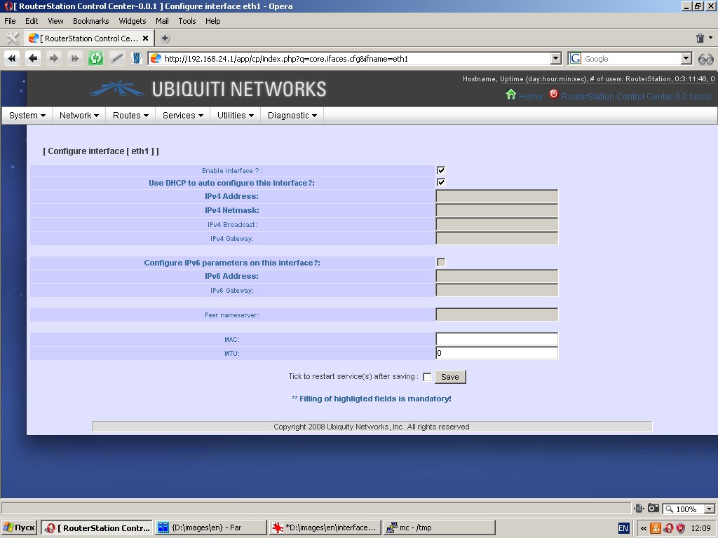
like eth0.1), aliases (using names like eth0:1), wireless interfaces, bridges (using names like ‘br’), bonded and dynamic interfaces. Here you can also edit settings of any existing interface.
This page displays interface loading charts. For wireless interfaces
this page also displays parameters of wireless environment. All charts
are drawn in near to real-time mode.
There are three types of interface configuration dialogues:
Configuration of Ethernet interfaces and aliases. When configuring
virtual interfaces and bridges this dialogue acquires some additional
fields. You can use DHCP for auto configuration or specify parameters
manually, such as IP-address, netmask, gateway, etc.
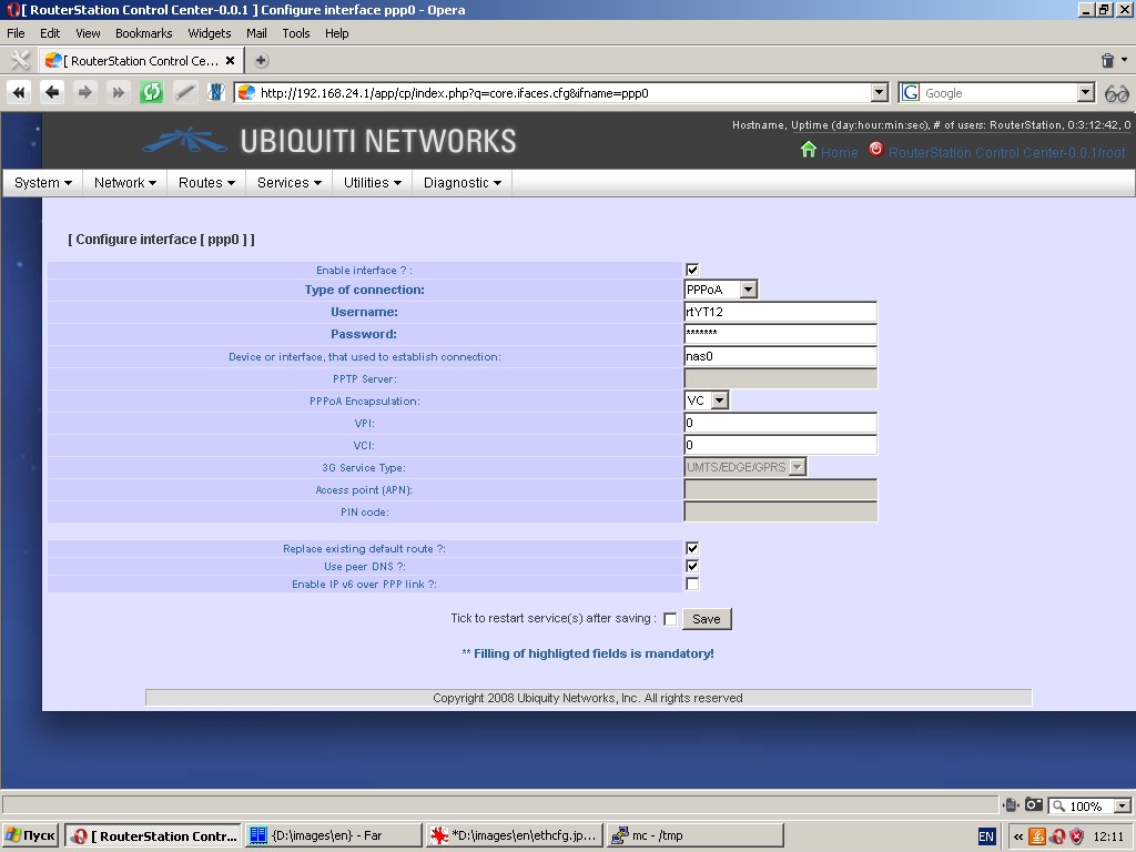
Configuration of dynamic interfaces (ppp-interfaces). This type of
interface configuration dialogue is used for dynamic connections with
PPP/PPTP/PPPoE/PPPoA protocols, where the device acts as a network
client. The following parameters can be configured: type of connection,
device or interface used to establish connection, etc.
Configuration of wireless interfaces. “IP settings” tab of this
dialogue is the same as Ethernet interface configuration dialogue.
“Wireless” and “Additional” tabs contain some specific parameters to be
set up for wireless devices: operational mode, current frequency,
modulation, encryption, etc.
Zones
Zone is a basic property of the firewall. Zones are logical networks
and the device is connected to a zone by at least one of its network
interfaces. A typical configuration contains two zones: world (Wan) and internal network (Lan). Besides, the device can be connected to other zones, e. g. to a demilitarized zone (Dmz).
The total number of zones is practically unlimited.
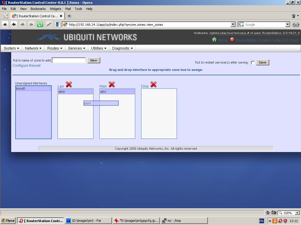
This page displays zones and contains easy zone control tools (for
creating, deleting zones and changing the content of each zone).
Originally all interfaces are unassigned and located in the “Unassigned
interfaces” box. Simply grab the required interface with the mouse,
drag it to the proper zone and drop there. You can re-assign interfaces
and make them unassigned in the same manner. Because firewall rules are
based on zones and their interfaces, be careful not to lose connection
to the device by moving an interface between zones.
Bridges
This page displays bridges and contains easy bridge control tools (for
creating, deleting bridges and changing the content of each bridge).
Please remember, that bridge names begin with ‘br’.
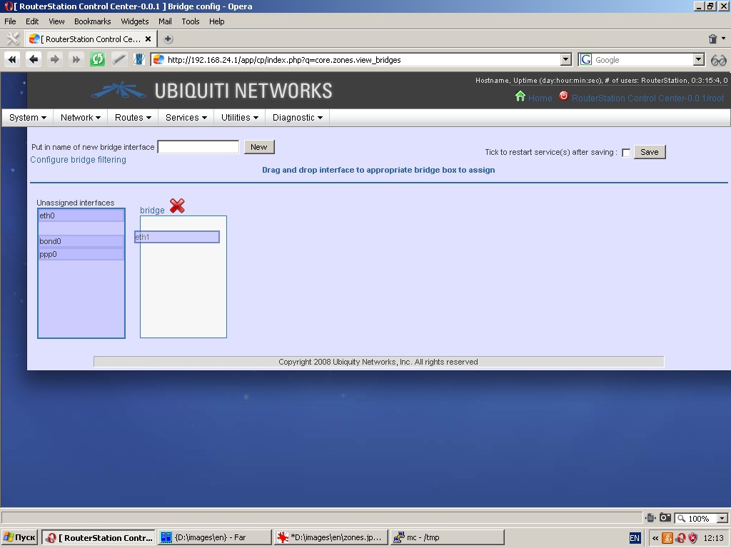
Originally all interfaces are unassigned and located in the “Unassigned
interfaces” box. Simply grab the required interface with the mouse,
drag it to the proper bridge and drop there. You can re-assign
interfaces and make them unassigned in the same manner.
Bonding
This page displays bonded interfaces and contains easy control tools
(for creating, deleting bonded interfaces and changing the content of
each one). Please remember, that bonding interface names begin with ‘bond’.
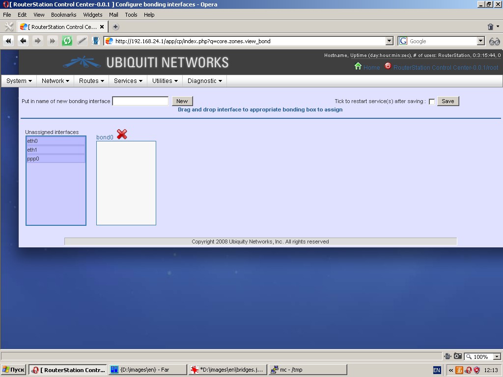
Originally all interfaces are unassigned and located in the “Unassigned
interfaces” box. Simply grab the required interface with the mouse,
drag it to the proper box and drop there. You can re-assign interfaces
and make them unassigned in the same manner.
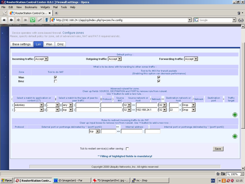
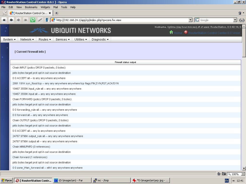
Firewall
The system has quite a powerful firewall and firewall control tools.
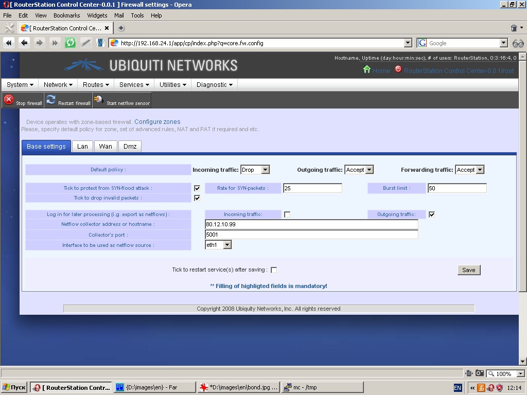
The following features of the firewall are available:
- protection from syn-flood attacks;
- export of traffic flow data going through the firewall in netflow v5 format
- Zone based firewall with automatic assignment of interfaces to the respective zone;
- Native address translation (NAT);
- Static address translation / port address translation (SNAT/PAT);
- Default policies for entire firewall and separately for each zone;
- Setting of flexible rules to accept, drop, reject or redirect
packets based on source and destination addresses, ports, protocol
matches (including application pattern matches (L7), MAC source
addresses, etc. Rules are set separately for each zone.
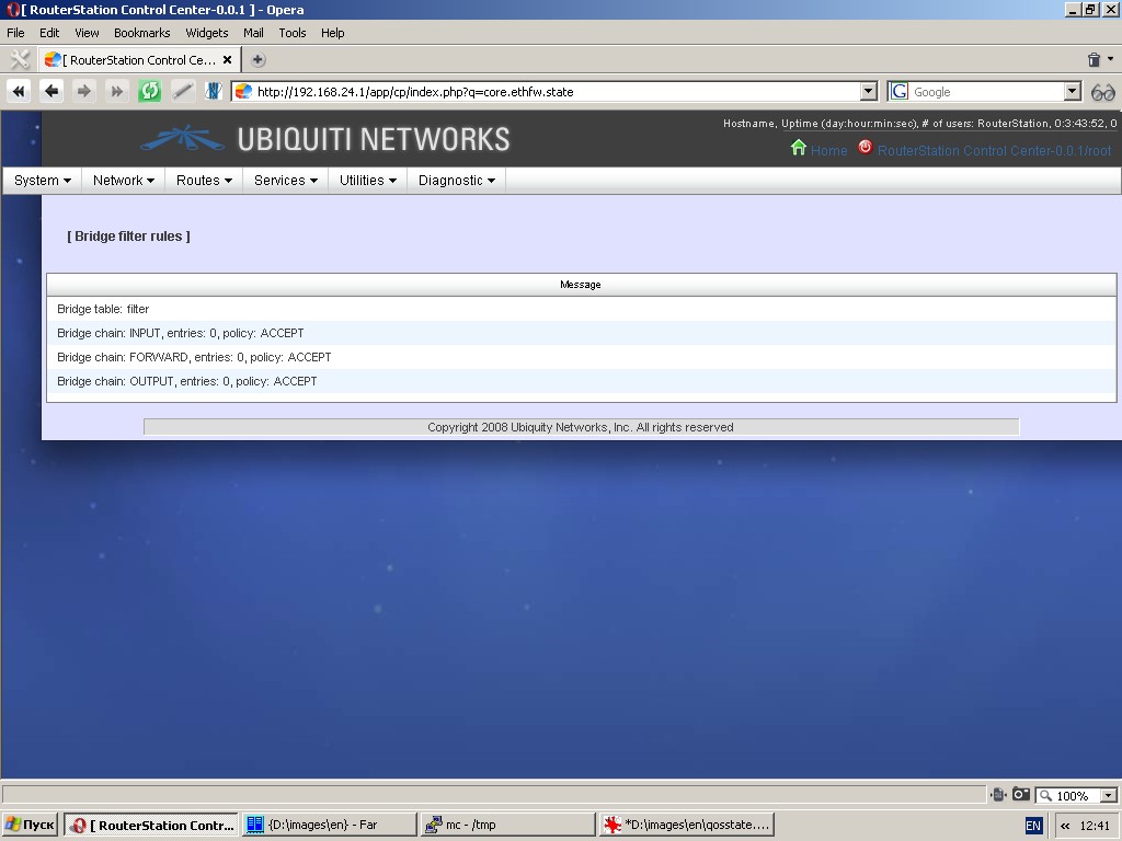
Bridge filtering
The system has bridge filtering tools at the level of Ethernet frames.
Please note, that you can use this function only if at least one bridge
is created in the system. Bridge filtering will only be applicable to
the traffic going through the bridge. Apart from bridge filtering you
can use such functions as redirection of Ethernet frames with IP v4 or
IP v6 payload to another Ethernet interface, creation of brouter, etc.
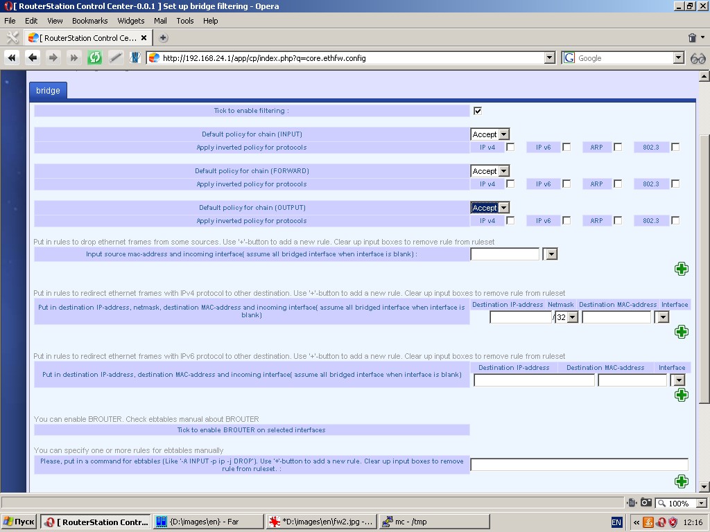
Bridge filtering settings are as follows:
- Default policies;
- Type of Ethernet frames (e. g. 802.3);
- Ethernet frames payload (IP v4 or IP v6, ARP-requests);
- List of MAC-addresses and/or interfaces, for which frames are to be dropped.
- Set of rules (IP destination address/netmask/MAC-address) for redirection of IP-packets to other interfaces;
- List of interfaces for creation of brouter (please refer to ebtables documentation).
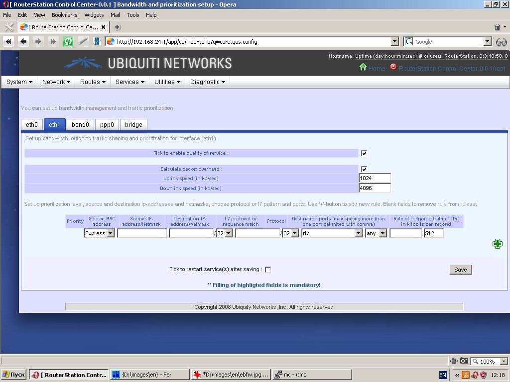
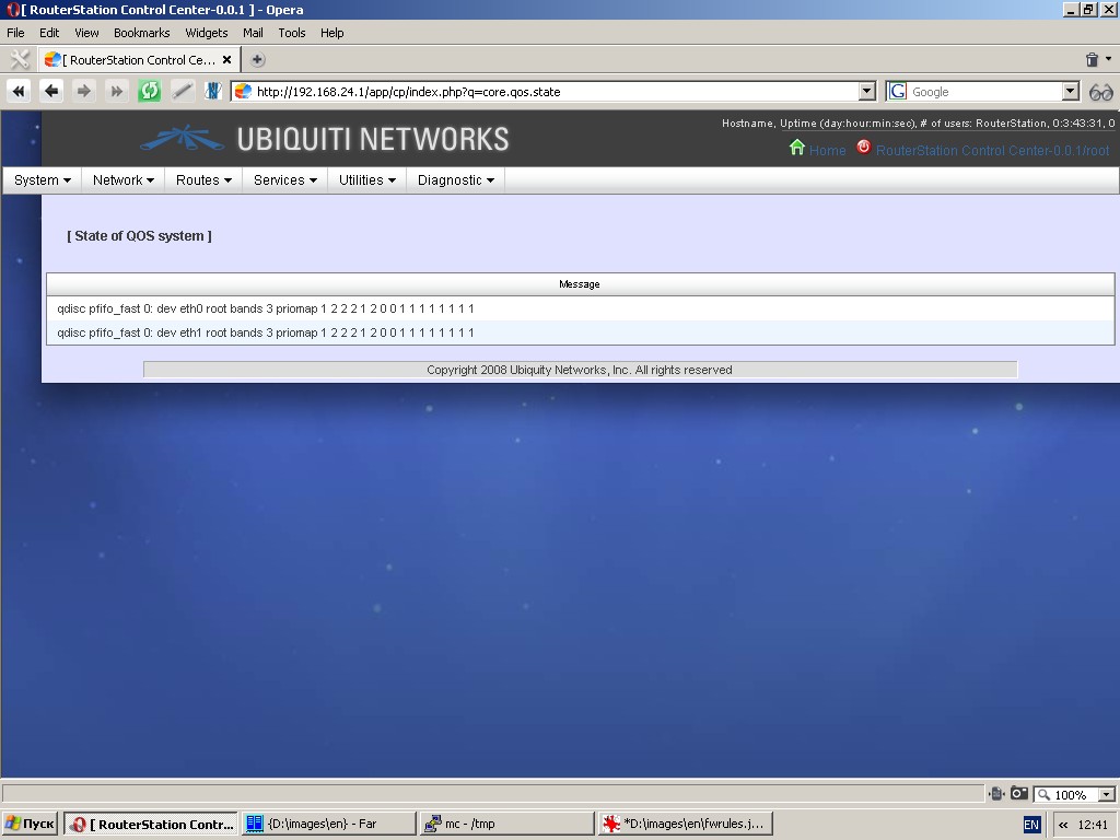
Bandwidth management and traffic prioritization
You can shape traffic, control quality of service (QOS) and manage bandwidth.
To do this, you can enable QOS for each interface, specify bandwidth,
define traffic classes, priorities for each traffic class and allocate
bandwidth.
Routes
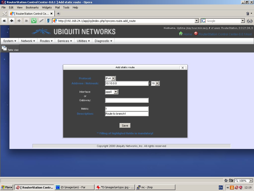
Static routing
You can specify various static routes by setting such parameters as
protocol, network (address and netmask), metric, interface or gateway
and route description.
Multipath-routing
The system is capable of multipath-routing and load balancing. To
activate this feature please assign at least two interfaces to Wan zone.
The following parameters are to be specified: interfaces, networks to be reachable through interface, etc.
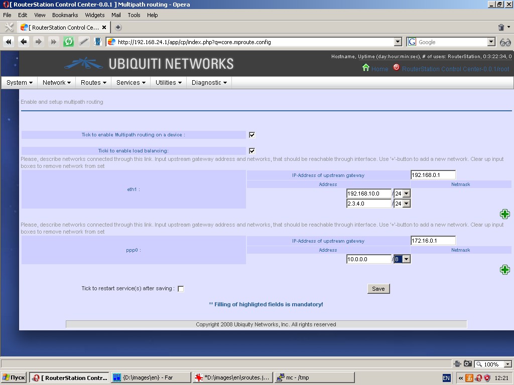
For more information please refer to relevant manuals.
RIP-router
The system has a pre-installed or an installable RIP-router and relevant control tools.
The following parameters are to be specified:
- Networks on which router operates;
- Interfaces on which split horizon is performed and/or which have router neighbors;
- Router neighbors;
- Redistribution of other protocol routes (static, OSPF, etc.);
- Metrics for such routes.
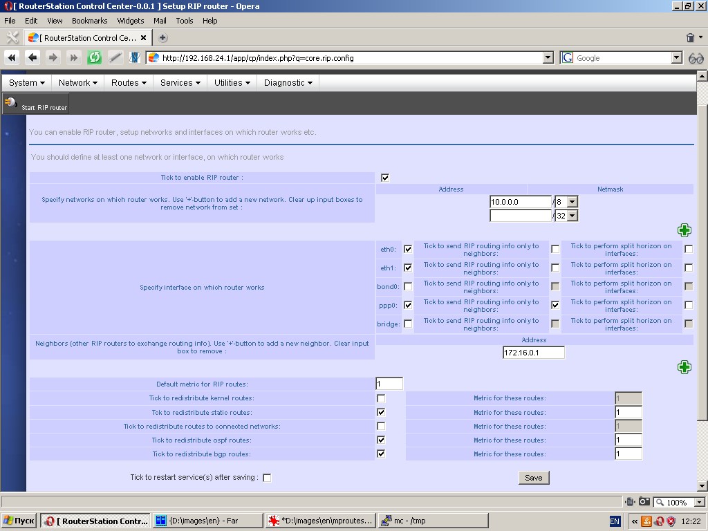
For more information please refer to relevant manuals.
OSPF-router
The system has a pre-installed or an installable OSPF -router and relevant control tools.
The following parameters are to be specified:
- Networks on which router operates and area ID’s;
- Router ID;
- Interfaces and their weights;
- Redistribution of other protocol routes (static, RIP, etc.);
- Metrics for such routes.
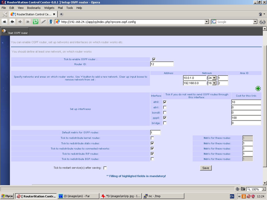
For more information please refer to relevant manuals.
BGP-router
The system has a pre-installed or an installable BGP -router and relevant control tools.
The following parameters are to be specified:
- Networks which router announces;
- Router ID;
- Autonomous system number;
- Router neighbors, their weights ad optional attributes;
- Redistribution of other protocol routes (static, OSPF, etc.);
- Metrics for such routes.
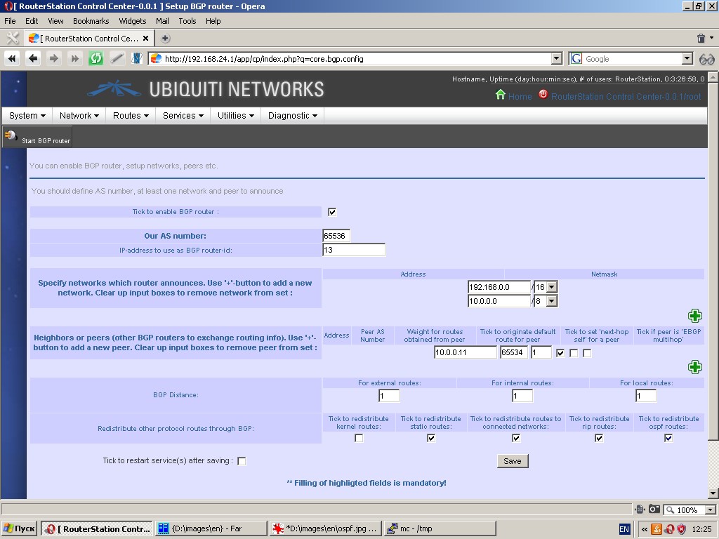
For more information please refer to relevant manuals.
Services
Time settings and synchronization
This page is used to specify system time, time zone and system time synchronization.
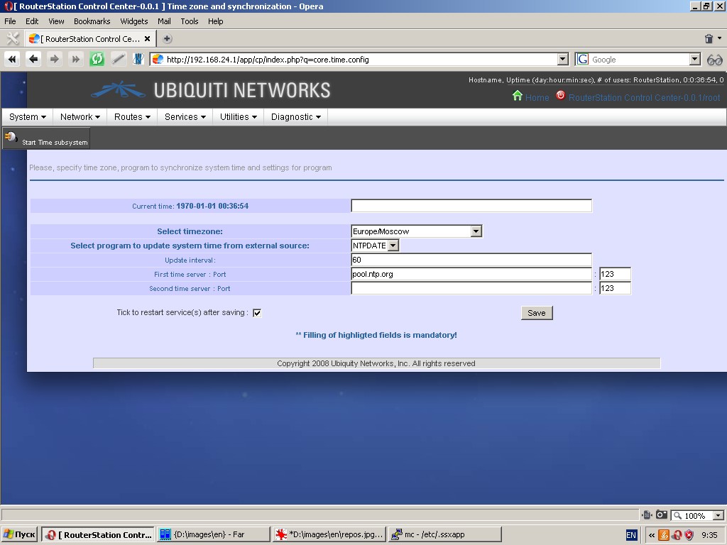
Time synchronization can be performed by client NTPDATE with one or more time servers (in this case please specify an update interval) or by NTPD server. In latter case the network time service becomes available for clients connected to the device.
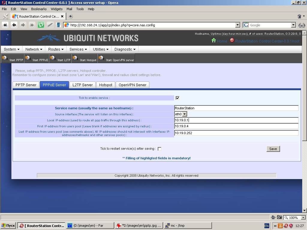
Access concentrator
By clicking on the “PPTP Server” tab you can specify such server settings as:
- Service name
- Source interface for the service to listen on
- Local IP address used to route all ppp traffic through this address (optional)
- First IP-address from users pool (not to be specified if IP addresses are assigned by a radius-server).
- Last IP-address from users pool (optional, not to be specified if IP addresses are assigned by a radius-server).
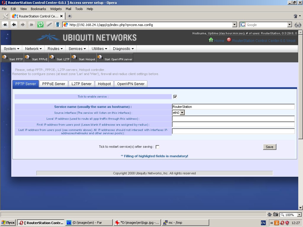
All specified IP-addresses should not intersect with interfaces’ IP-addresses/netmasks and pools of other services.
“PPPOE Server” tab contains the same settings.
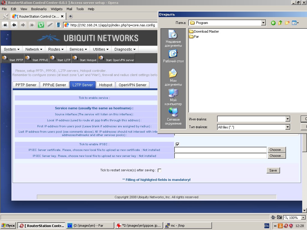
“L2TP Server” tab contains the same settings plus the ability to enable
IPSEC for connections. If IPSEC is supported, you should upload server
certificate and key.
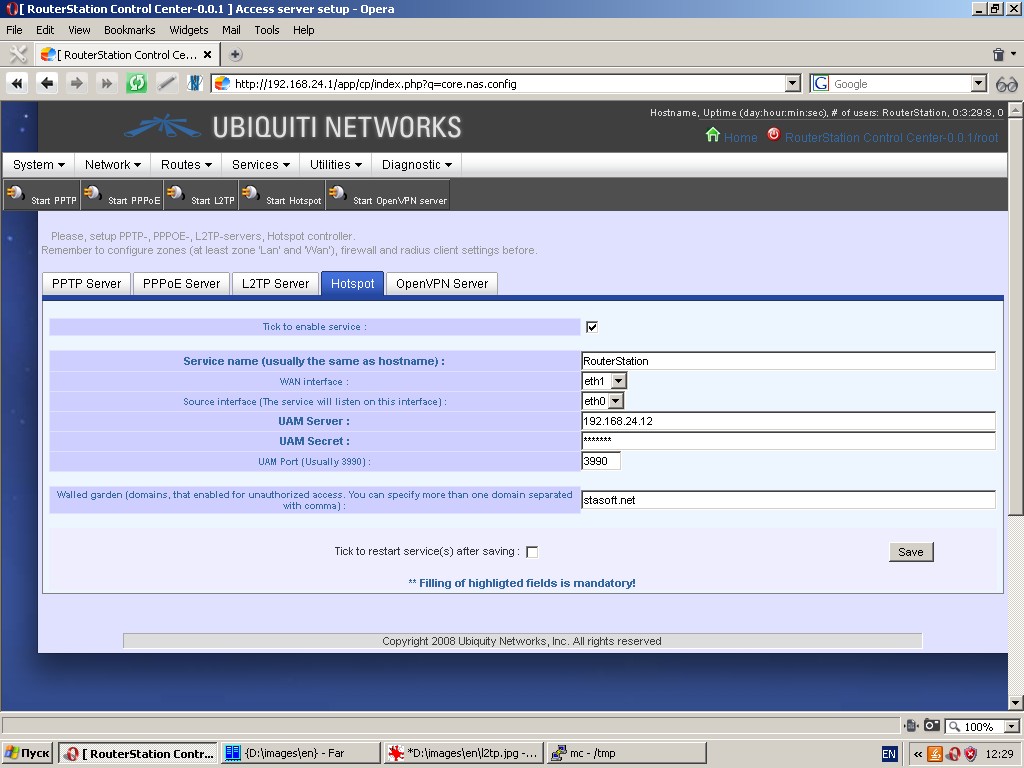
“Hotspot” tab contains control tools for chillispot program.
The following parameters can be specified: service name, WAN interface,
source interface (from zone Lan), UAM server and port, secret phrase
for UAM server. Chillispot provides walled garden (domains enabled for
unauthorized access).
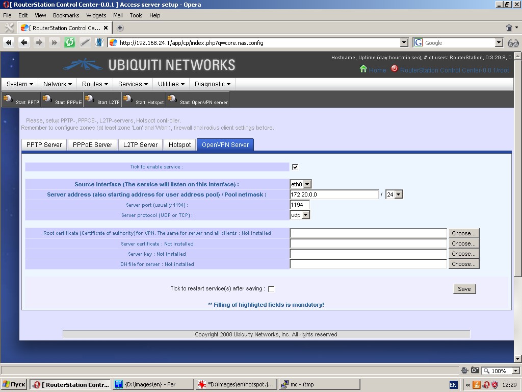
“OpenVPN Server” tab contains control tools for OpenVPN server. Here
you can set up the source interface for the service to listen on; user
address pool; server port and protocol; and upload root certificate
(certificate of authority), server certificate and key, DH file for
server.
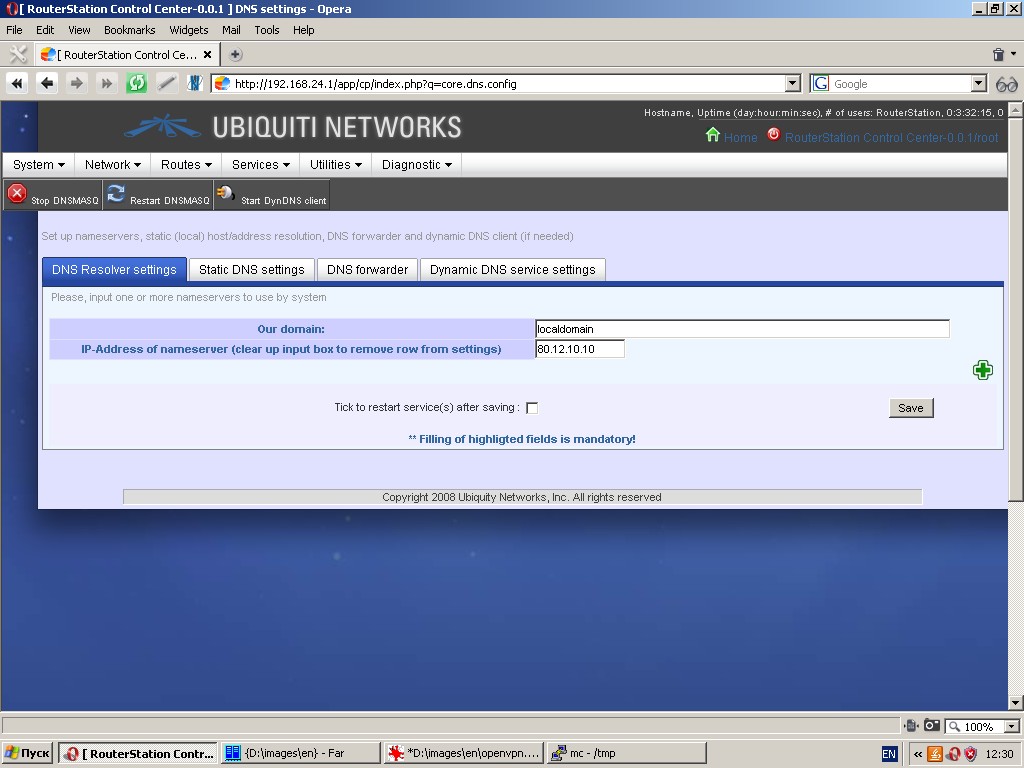
Domaine name resolution
Under the tab “DNS Resolver settings” you can specify the domain, in
which the device operates, and one or more nameservers to be used by
the system.
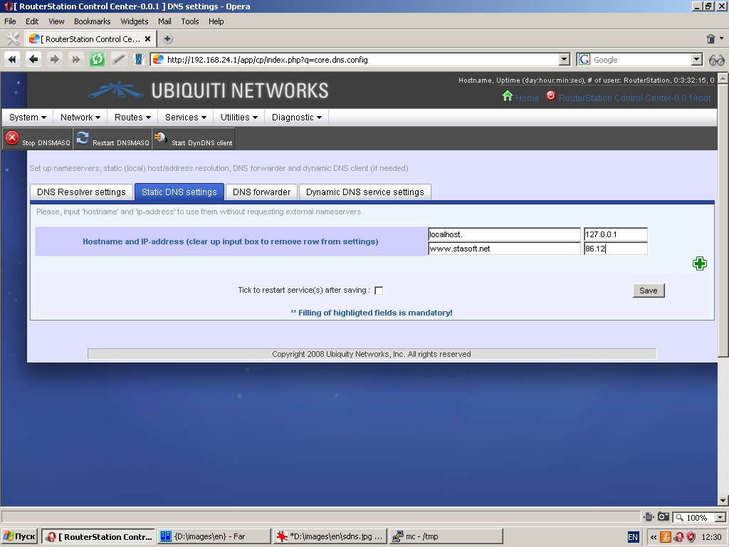
Under the tab “Static DNS settings” you can specify static pairs of
'hostname' and 'IP-address' to be used without sending requests to
external nameservers (i. e. you can assign any full qualified domain
name to any IP-address).
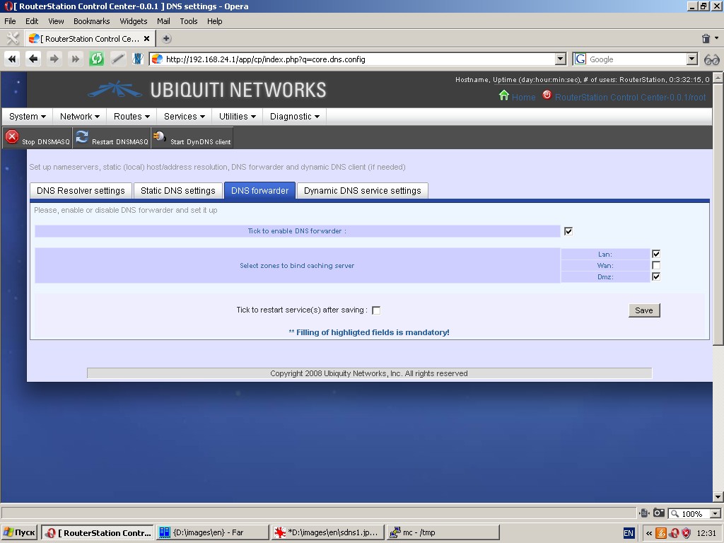
Under the tab “DNS forwarder” you can select zones to bind caching server.
Under the tab “Dynamic DNS service settings” you can choose DynDNS
service provider, external interface to obtain an IP-address, specify
how often IP-address is to be checked and DNS updated, service user
login and password.
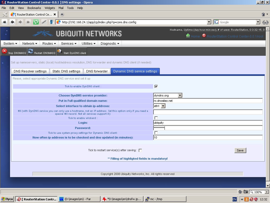
To be able to use dynamic DNS service you must be registered with the chosen service provider.
DHCP settings
“DHCP Server” tab contains DHCP-server setting tools (DHCP is the
server, which automatically assigns IP-addresses at the requests of the
clients).
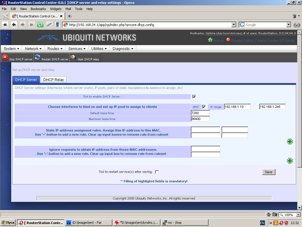
The following parameters are to be set: interfaces to bind on and
IP-pool to assign to clients, pairs of static MAC-address/IP-address to
assign, list of MAC-addresses to be ignored, etc.
“DHCP Relay” tab contains relay settings (host to relay and other settings).
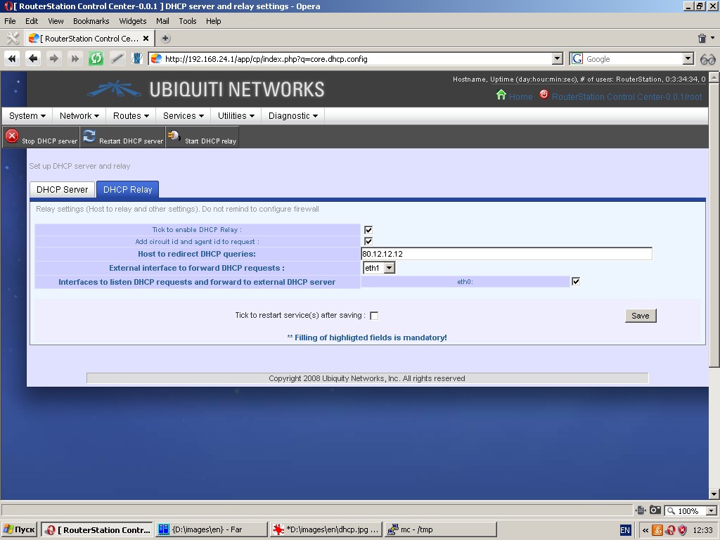
The following settings are to be specified: host to redirect DHCP queries, circuit ID and agent ID, etc.
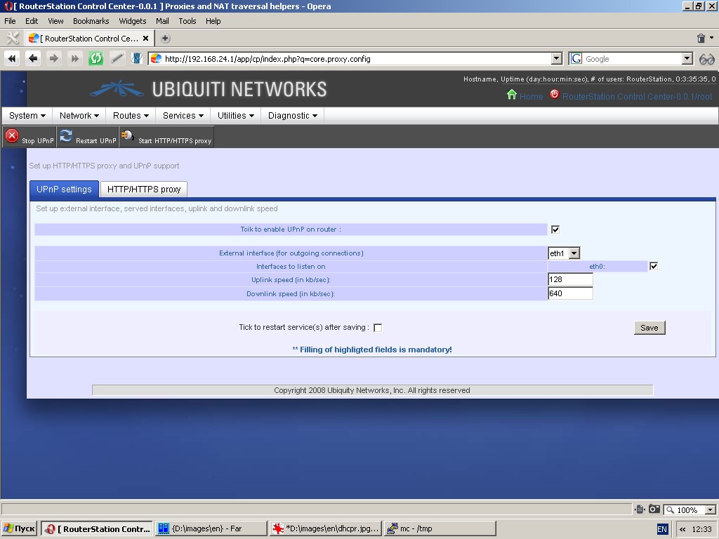
Proxy and NAT traversal
Under the tab “UPnP settings” you can set up UPnP support. The
following settings are to be specified: external interface for outgoing
connections, interfaces to listen on and uplink/downlink speed.
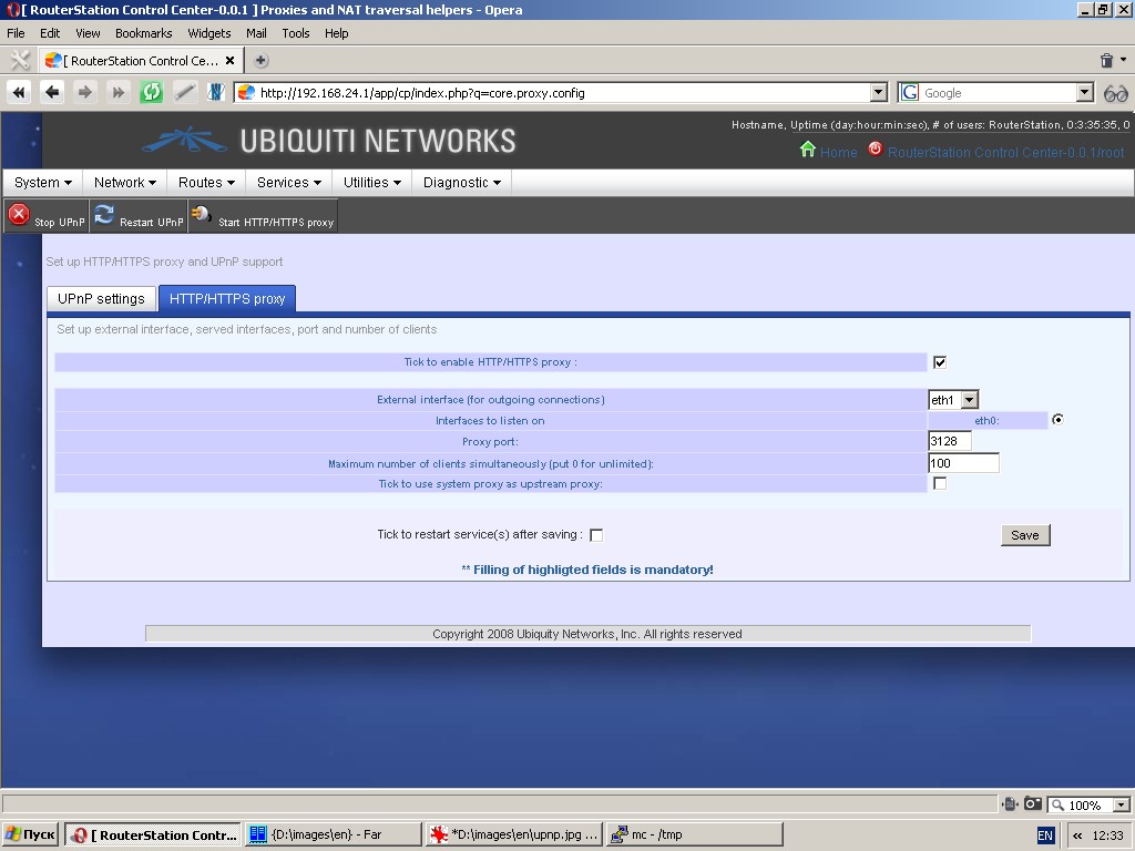
“HTTP/HTTPS proxy” tab contains proxy setting tools. You can select one
external interface for outgoing connections, an internal interface to
listen on, specify proxy port, maximum number of clients simultaneously
and use system proxy as upstream proxy.
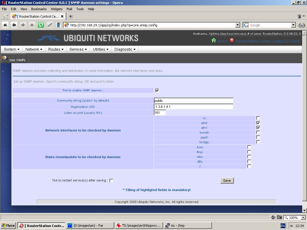
SNMP daemon
This page contains SNMP-server settings. SNMP deamon ensures monitoring
of network interfaces and device partitions by client applications
using SNMP ver. 2 protocol. Additional settings to be made are
community string, OID and port to listen on.
Utilities
Image backup and restore from image
Backup settings
By using “Backup folders and files” tab you can specify a set of
folders to backup, subfolders to exclude from backup process,
compressor and path to keep a compressed image. Remember that you can
specify more than one folder by clicking the ‘+’ button.
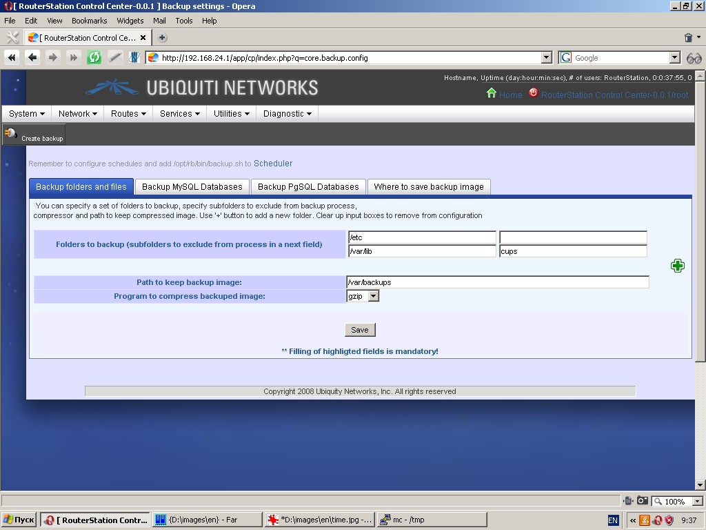
One of the settings is selection of program to compress backup image (gzip or bzip2).
You must also specify a path (filesystem directory) to keep backup image. Don’t use network shares for this directory.
Remember that to be able to perform backup, your system must have an
installed rsync software package and at least one compressor: gzip or bzip2.
Under the tab “Where to save backup image” you can specify what to do
with a backup image after saving. You can move backup image to remote
server by means of either built-in ftp-client or scp/rsync
protocols (requires installation of respective software packages). You
can also move or copy backup image to another device partition (another
physical storage) or network partition.
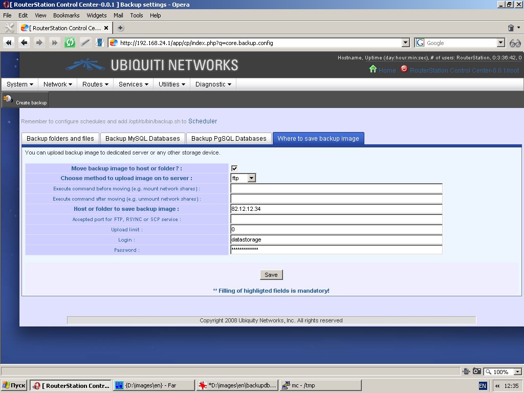
Settings to be made are: host or folder to save backup image, accepted
port, type of protocol, what commands are to be executed before and
after moving (e. g. mount / unmount), etc.
Remember that backup process is launched by backup.sh command.
Execution time and periodicity are to be specified under the menu item
“Schedule”. Backup can also be forcibly executed by clicking the
toolbar button “Create backup”.
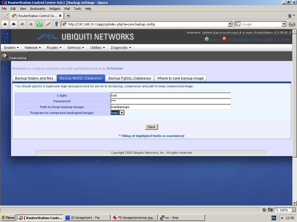
In the event of installed MySQL and/or PostgreSQL client(-s) and
server(-s) the system is capable of performing full backup of all
databases. In this case you should specify a superuser login and
password for the server to do backup, compressor and path to keep
compressed image. Backup images will be handled in the same manner as
images of files and folders.
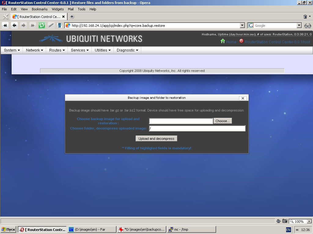
Restore from image
You can upload and decompress backup image specifying a folder for decompression of uploaded image. Backup image should have .tar.gz or .tar.bz2
format. Please remember that after decompression current files will be
replaced by files from the backup image, whereas the files, that are
not present in the backup image, will be untouched.
Factory default settings
When you choose “Yes”, the current configuration will be overwritten by factory default settings.
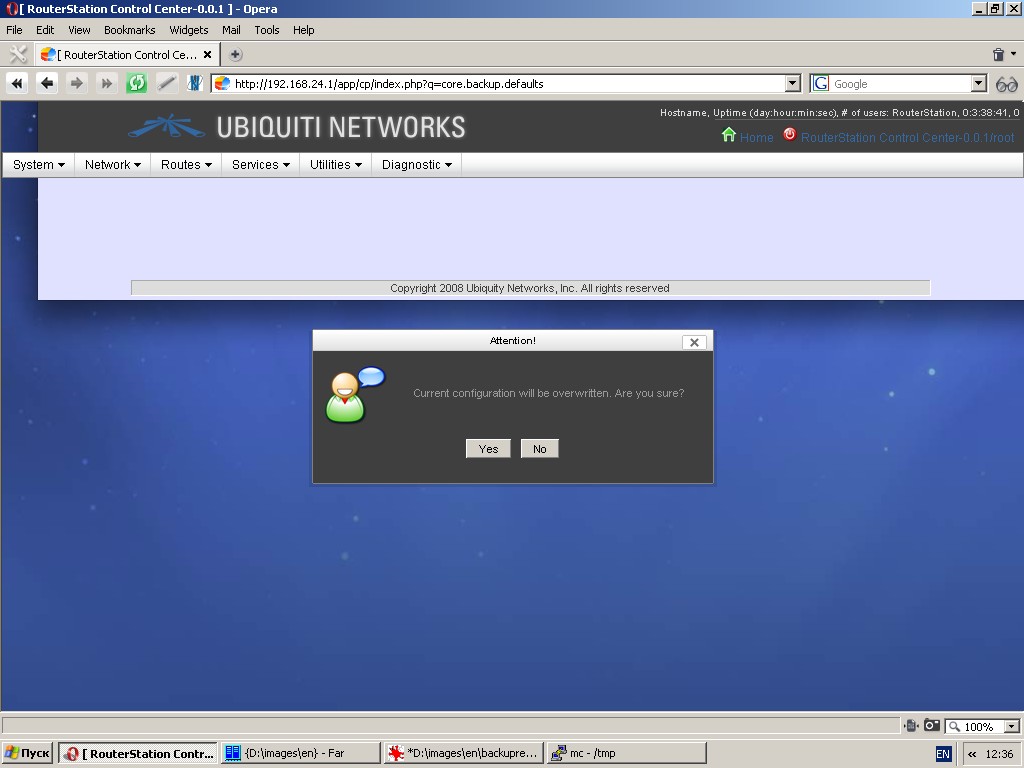
Use this function with utmost care!
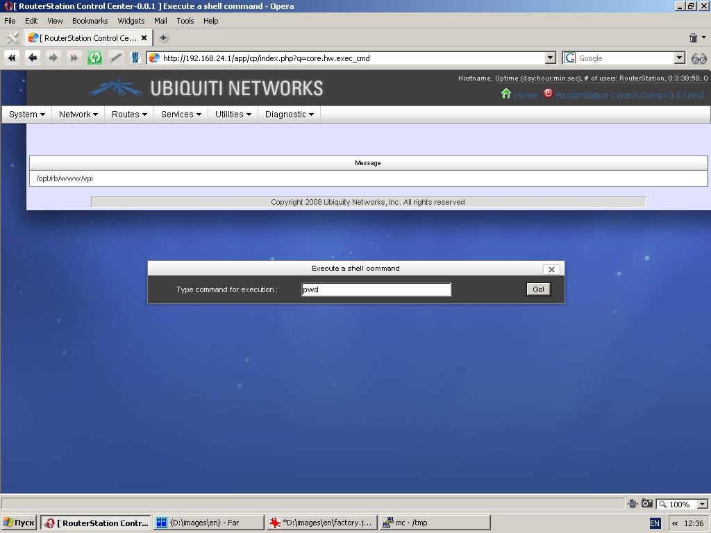
Execute command
You can execute any command as if you are using an operating system
console. You will see output in table “Message” (Don’t use “Enter” key
to execute command. Click “Go!” button in the dialogue window). Use this function with utmost care!
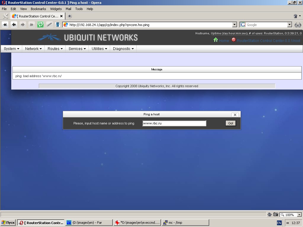
Ping host
Pings specified IP-address or hostname. You will see output in table “Message”.
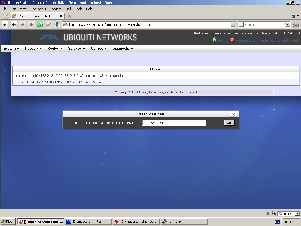
Traceroute
Performs rout tracing of specified IP-address or hostname. You will see output in table “Message”.
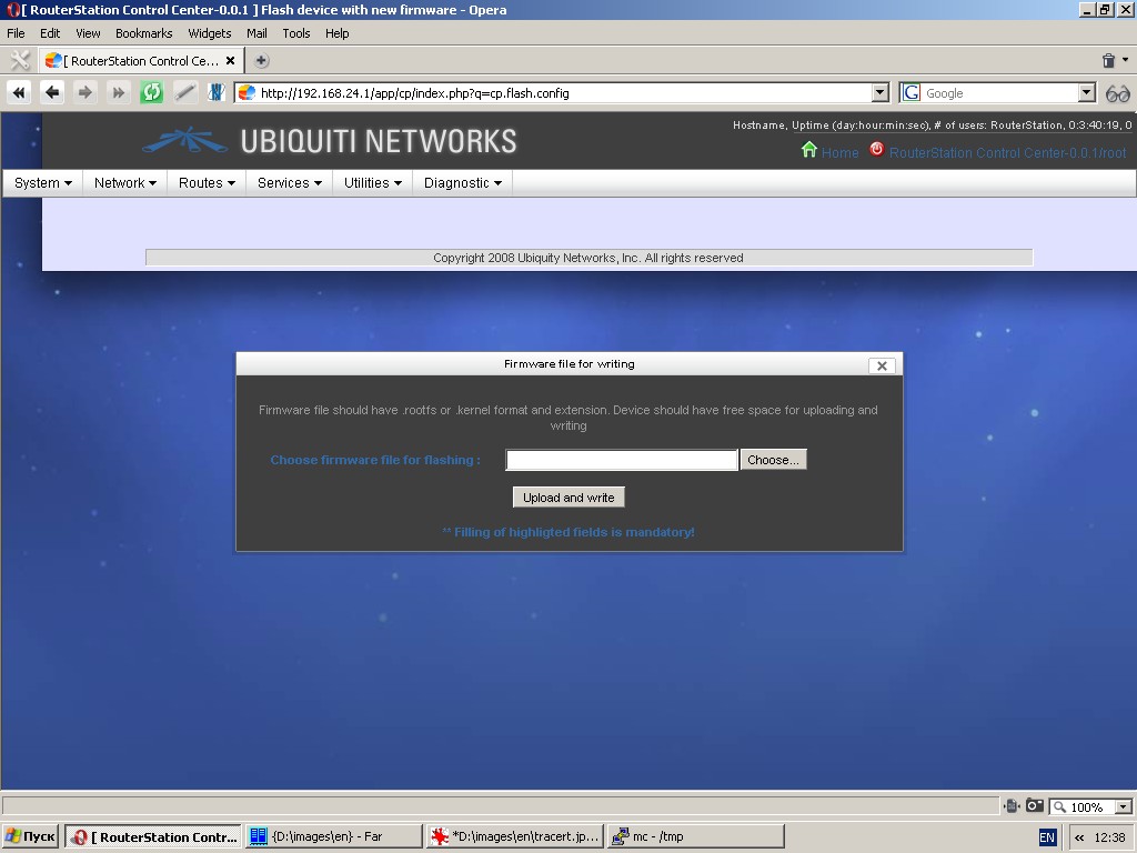
Flash firmware
The device has two partitions: for kernel and for root filesystem. You
can upload a new image for one partition at a time and flash it. Thus,
you can flash new firmware for the whole system in two steps only. To
do this, you should have specially created images for kernel and rootfs
partitions. If you are not sure what you are doing, please don’t ever use this function.
Reboot system
This function reboots the system. Please wait 2 – 3 minutes before you can relogin.

Halt system
This function halts the system. Once you halted the system, it can be booted only after you switched the power off and on again.

Diagnostics
Brief info
This function displays basic system and device information: OS, kernel
and distributive, CPU type and parameters, RAM size, information about
drives and controllers, etc. You can also see a system load chart (CPU
usage, RAM usage, etc.).
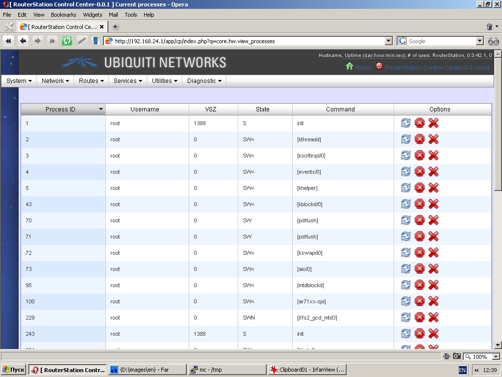
Processes
This function displays running processes in list-form (ps ax). You can
send one of the following three signals at a time to any listed
process: HUP, TERM and KILL. Please use these signals with utmost care.
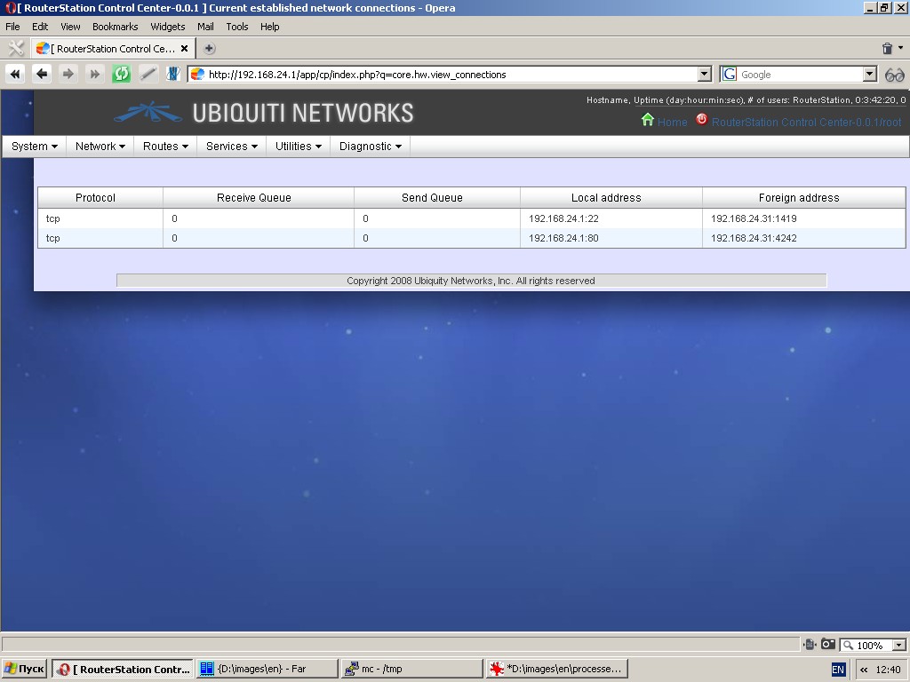
Connections
This function displays a list of established connections (netstat -na). The output is refreshed automatically.
Routes
This function displays kernel route table in list-form (netstat -nr). The output is refreshed automatically.

ARP table
This function displays kernel ARP table in list-form (successfully
resolved pairs of MAC-address and IP-address). The output is refreshed
automatically.

Firewall tools
This function displays current rules for all chains (iptables -vL).
QOS state
This function displays current traffic management rules.
Bridge filtering state
This function displays current bridge filtering state (ebtables -vL)
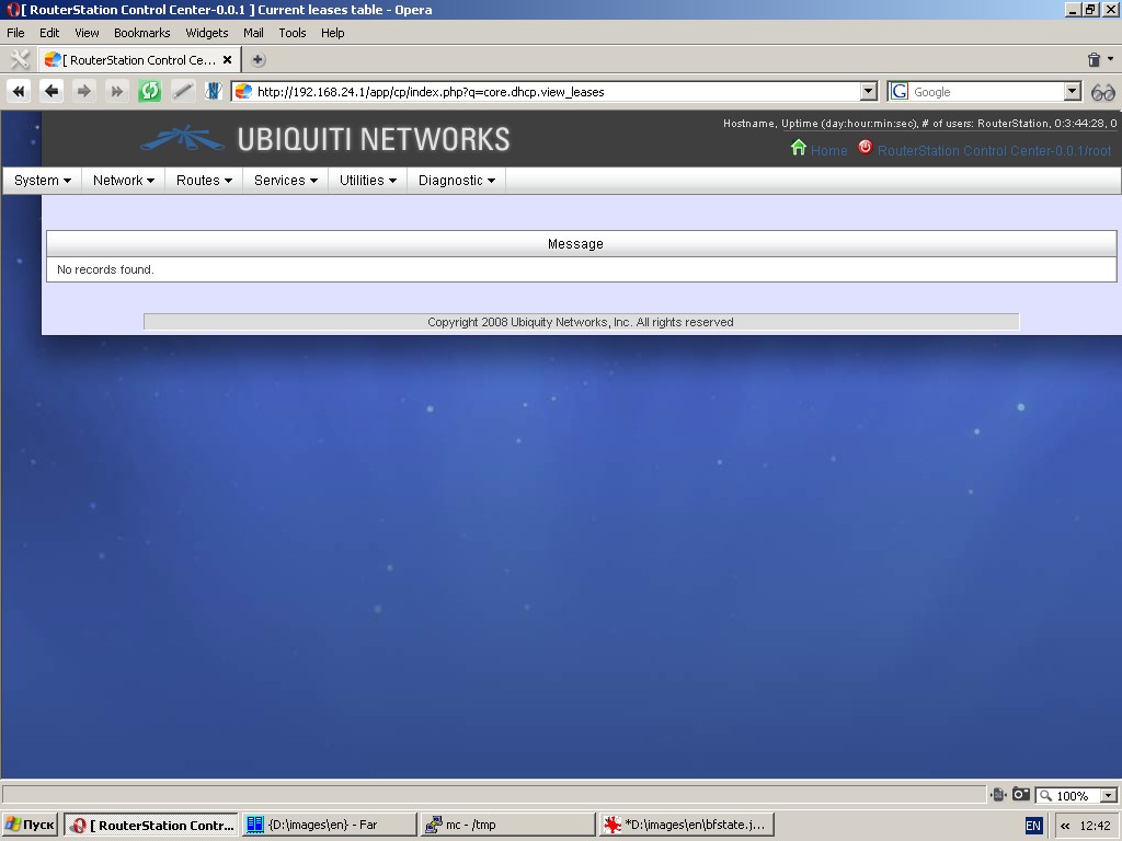
DHCP leases
This function displays IP-addresses and their MAC-addresses leased through DHCP server.
Packet capture
You can capture some traffic to analyze or debug flow. Use this
function with care, because it loads CPU, network card and memory.
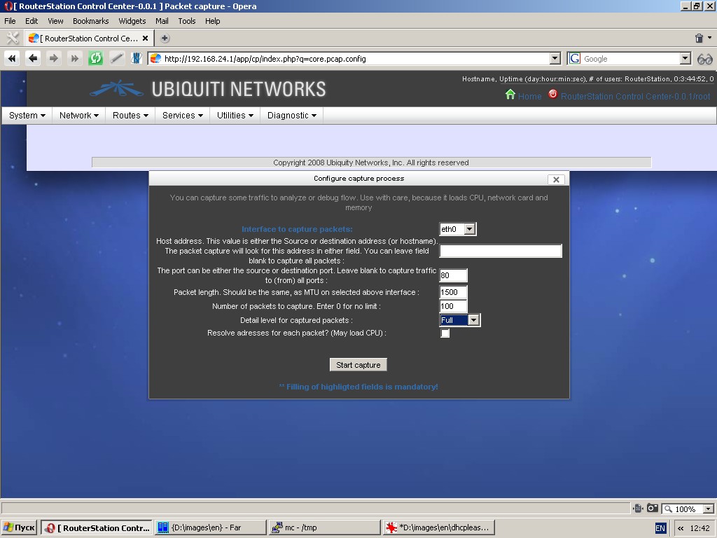
In fact, this function uses tcpdump software to capture and analyze traffic.
To set up this function you must specify an interface to capture
packets. As an option, you can also specify a fully qualified domain
name or an IP-address. In this case the system will capture only the
packets, in which source or destination matches the entered IP-address
(in terms of IP v4 protocol). In the event an IP-address is not
specified, the system will capture all traffic flowing through the
given interface and matching other values (if any).
You can also specify port number as an extended criterion for traffic
capture. In this case the system will capture packets, in which source
port or destination port mach the specified value.
Make sure the value “Packet length” matches MTU size for a selected interface.
Specify the number of packets to capture. “0” is to be used for an
unlimited number. Capture process can be halted only by clicking the
“Stop capture” button.
You should detail level for captured packets other than “Normal” used
by default and, as an option, resolve IP-addresses for each packet.
Remember that this option is operational only if a fully qualified
domain name is specified in the field “Host address”. Using this option
may extremely load the CPU.
General recommendations for traffic capture system:
Try to type in exact IP-addresses and ports. Don’t use the option of
resolving addresses for each packet. Specify the number of packets to
capture.
When the capture process is halted, you can download the file with captured and processed traffic to a local PC.
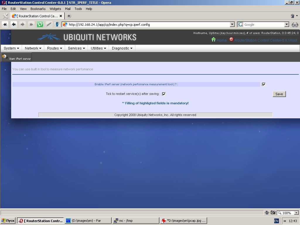
Network performance measurement server
The system uses iperf software in server mode. You can measure network
performance by launching iperf in client mode from a connected PC.
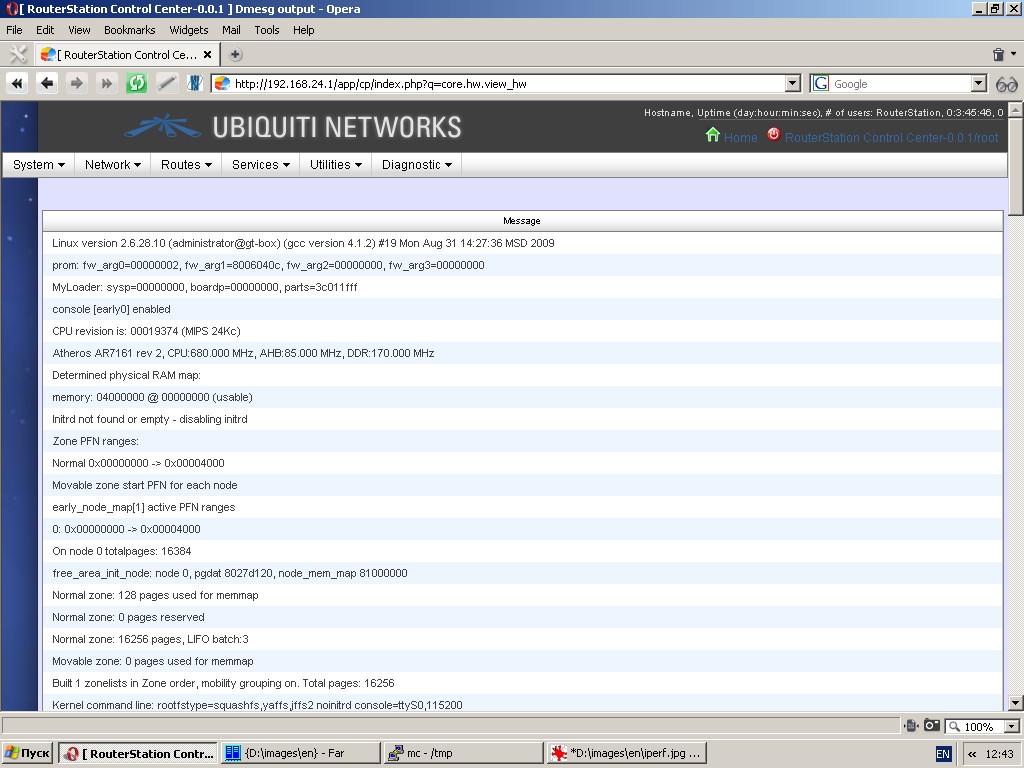
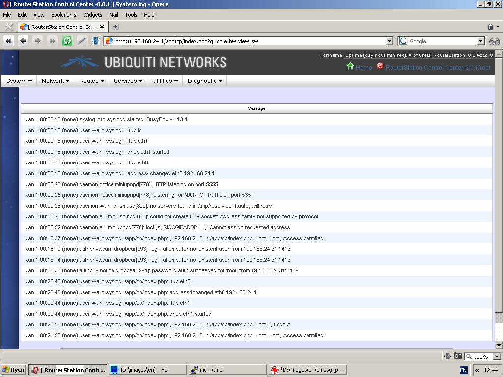
System logs
Hardware log displays dmesg output.
System log shows the contents of the log-file /var/log/messages.
How to build OpenWRT based firmware with NETSHe for Ubiquity RouterStation
Note: This document describes only the firmware assembly steps, which
differ from standard firmware assembly procedure for OpenWRT Kamikaze.
For standard firmware image assembly procedures please refer to
Ubiquity web sites
(http://wiki.ubnt.com/wiki/index.php/RouterStation_OpenWRT_Setup_Guide
http://www.ubnt.com/forum/showthread.php?p=54837) and OpenWRT web site
(http://wiki.openwrt.org/doc/howto/buildroot
https://dev.openwrt.org/wiki/GetSource).
We proceed from the assumption, that you are aware of the manner and procedure of firmware assembly based on OpenWRT tools.
Further all references to filesystem will be made with regards to Kamikaze root directory.
-
Create directory for OpenWRT Kamikaze and change current directory (e. g. cd ~; mkdir kamikaze; cd kamikaze)
-
Download OpenWRT source code (svn co svn://svn.openwrt.org/openwrt/trunk)
-
Download source code of OpenWRT packages (svn co svn://svn.openwrt.org/packages)
-
Update source tree (svn up)
-
Download archives from
http://stasoft.net/files/netshe-openwrt-build.tar.bz2 and
http://stasoft.net/files/php5-openwrt-build.tar.bz2
-
Besides, you can also download a configuration file for image
assembly http://stasoft.net/files/ubnt-rs-openwrt-config. This file was
created for a development version of OpenWRT and represents a slice at
a given date. You may have troubles with current or future slices of
development version. Use this file only as a sample.
-
Ignore this step if you have not completed step 6. Otherwise, copy
downloaded file to kamikaze root under the name .config (e. g. cp
~/ubnt-rs-openwrt-config ~/kamikaze/trunk/.config)
-
Remove php5 directory in packages/lang directory (e. g. rm -rf ~/kamikaze/packages/php5)
-
Unpack archive php5-openwrt-build.tar.bz2 to directory packages/lang
(e. g. cd ~/kamikaze/packages/lang; tar -xjf
~/php5-openwrt-build.tar.bz2).
-
Make sure that directory packages/lang/php5 exists.
-
Unpack archive netshe-openwrt-build.tar.bz2 to directory
packages/admin (e. g. cd ~/kamikaze/packages/admin; tar -xjf
~/netshe-openwrt-build.tar.bz2).
-
Make sure that directory packages/admin/netshe exists.
-
Change directory to kamikaze (e. g. cd ~/kamikaze)
-
Create a symbolic link from trunk/package to directory packages (e. g. ln -sf packages ~/kamikaze/trunk/package/packages)
-
Change directory to trunk (e. g. cd ~/kamikaze/trunk)
-
Type in make menuconfig
-
Choose Atheros AR71XX/AR7240/AR913x from Target System menu (if you don’t use our config file).
-
Choose Ubiquity RouterStation from Target System menu (if you don’t use our config file).
-
In Adminisration menu put asterisk at item netshe (if you don’t use our config file).
- Choose additional software packages and build options.
-
Type in and execute make to assembly image.
-
Flash assembled software to device as described in User Manual.